 With today’s energy pricing, proactive plant managers are looking to recover any flash steam. Get this article on best practices.
The non-modulating steam system’s operational design allows the condensate and flash steam to be recovered in a flash tank system. This flash steam recovery system differs from a modulating steam system as discussed in Best Practice No. 26.
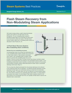
Condensate/flash steam (two-phase flow) discharging from a non-modulating steam system process can be recovered in a flash steam system or high-pressure condensate return system. Non-modulating steam condition means there is no control valve modulating steam flow to the process. If there is a control valve, the steam control valve always maintains a steam pressure to the process above the pressure in the condensate recovery system. A non-modulating process steam system provides a constant steam pressure to the process, thus providing a constant pressure differential across the steam traps or condensate discharge control valve. (See Figure 1 below on this page.)
Review of non-modulating processes
The two-phase flow (flash/condensate) from the process discharge can be directed to the pressurized flash tank for separation. The flash/condensate separation process separates the flash steam and condensate, leaving no entrainment of condensate into the flash steam. The flash steam can then be delivered to a lower-pressure steam line. This method is referred to as a cascading flash steam system. In a high-pressure condensate return system, the percentage of flash steam is greatly reduced by the high pressure in the condensate return line, and typically the flash steam is used for the deaerator steam consumption.
Examples of non-modulating steam processes:
Flash recovery system
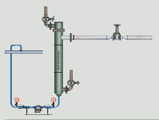
The steam systems don’t have a modulating steam control valve for the process, or if there is a control valve, the steam control valve always maintains a steam pressure to the process above the pressure in the condensate recovery system. There is always a higher steam pressure to the process than the condensate return line, which will provide a constant pressure differential across the steam traps or condensate control valve. (Figure 2)
With proper sizing and installation of a flash tank, the flash steam may be used for the heat exchanger device to heat air, water, or any other liquid, or it may be used directly in processes with lower-pressure steam requirements. Flash steam can be generated directly by discharging high-pressure condensate to a lower-pressure steam system. This practice is very seldom used in industrial applications. The best practice is to use a flash tank to:
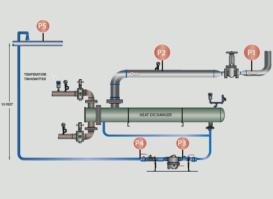
Flash tanks can be mounted either vertically or horizontally, but the vertical arrangement shown in Figure 3 is the preferred method because it provides better separation of steam and condensate and results in the highest possible flash steam quality.
The most important dimension in the design of vertical flash tanks is the internal diameter, which must be large enough to ensure a low discharge velocity of flash steam to minimize condensate carryover. Also, the tank sizing requires sufficient surface area for the release of the flash steam from the condensate. If the condensate return line is properly sized, the condensate will release the flash steam in the condensate line; therefore, the flash tank becomes a separator tank (flash and condensate). Outlet velocities from the flash tank should not exceed 3,000 feet per minute. Unfortunately, most condensate lines found in industrial operations are not properly sized; therefore, the flash tank has to provide the proper area for the condensate to release the flash steam.
In Figure 3, the flash steam is being used in a cascade steam system; that is, the flash steam is being delivered to the lower-pressure steam system. The steam demand must always be greater than the amount of flash steam available to prevent the low-pressure steam system from becoming over pressurized. A safety relief valve should always be installed at the top of the flash tank or steam line piping to preclude an over pressurized situation in the steam line. In a typical cascade flash steam system, the flash steam generated is generally less than the demand for a low-pressure steam system. A pressure-reducing valve or makeup steam valve is added to the system to ensure the low-pressure steam system maintains the correct operating pressure.
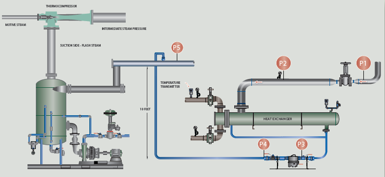
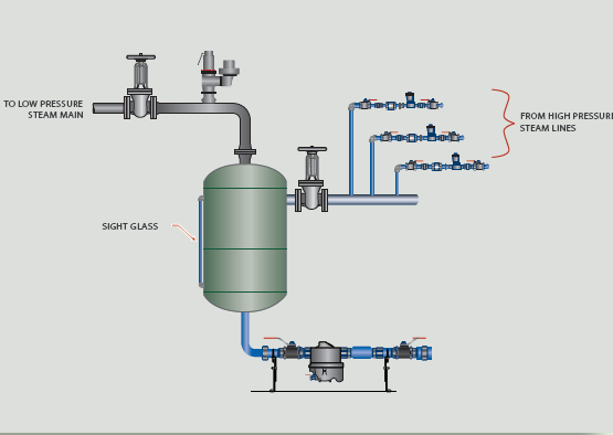
A large number of plants do not have a need for low-pressure steam; therefore, the cascade steam system is not a benefit. Another method to recover the flash steam is to use a thermocompressing system. (Figure 4)
Thermocompressing takes the low-pressure steam and produces a higher, usable steam pressure. The thermocompressor is a very simple device that has been in existence for many years. It has a nozzle where high-pressure steam is accelerated into a high-velocity fluid. The high velocity entrains the low-pressure steam from the flash tank by momentum transfer and then recompresses it in a divergent venture. The result is an intermediate steam pressure that is useful to the plant operation.
Flash tanks are considered pressure vessels and must be constructed in accordance with ASME and local codes.
Road map
For Steps to Designing a Flash Tank and detailed examples, please fill the form and check your email.