


/Digital%20montage%20(1).jpg?width=1920&name=Digital%20montage%20(1).jpg "Digital montage (1)")
by Paul Lesnau, on 10/8/20 8:45 AM
Within the range of API plans used in Northern California manufacturing organizations, API Plan 32 is a relatively uncomplicated design. It provides a clean flush of plant water or other compatible fluid to the seal chamber from an external source. Additionally, a close-clearance throat bushing helps control seal chamber pressure by limiting the flush that migrates past the bushing to the pump chamber. With that level of relative simplicity, API Plan 32 troubleshooting shouldn’t be a headache at all.
API Plan 32 delivers flush fluid to the seal chamber
However, with a relatively simple design and straightforward process applications, it’s not as simple as “install it and forget it.” Knowledge and hands-on experience are still important in maintaining seal support system reliability—an increasing concern for any Northern California refinery facing the reality of a workforce where younger technicians are entering the industry just as well-versed as their older counterparts.
Here, we explore three areas of focus—pressure, flow, and temperature—and how to conduct API Plan 32 troubleshooting for each.
Issues that May Require API Plan 32 Troubleshooting
While many experienced technicians can vouch for the reliability of API Plan 32 in mechanical seal support system applications, once installed, that integrity must be maintained. If issues arise, here's what to do.
Inability to Maintain Required Flush Fluid Pressure
API Plan 32 requires the external flush fluid to be delivered at least 15 psi (1 bar) higher than the stuffing box pressure. Pressure varies by application and can range anywhere from 29 psi (2 bar) to 129 psi (8.9 bar) or even higher. If there’s a change in pressure, it’s likely to be a decrease. Here’s what to look for when troubleshooting pressure problems.
- Unexpected, emergency need for water or a major leak elsewhere in the plant
- Unintentional full or partial closure of the flush supply valve
- Crimped or damaged tubing that supplies flush fluid to the seal chamber
- Flush fluid contaminants or particulates clogging an orifice or flow control valve
- Damaged or deteriorated throat bushing, increasing the volume of flush fluid migrating to the pump chamber
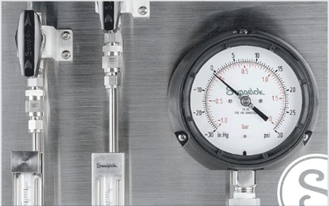
 Proper instrumentation alert to pressure problems and help identify the root cause.
Inability to Maintain Required Flush Flow
This problem is closely related to pressure. A pressure drop impacts flow and all of the diagnostics mentioned under pressure should be considered. The quality of flush fluid should also be looked at carefully. If it’s plant water, minerals can slowly build up in flow control valves and gradually reduce flow and pressure. If the flush is a solvent compatible with the process fluid, or heavy coker gas oil (HCGO) or heavy vacuum gas oil (HVGO), contaminated flush fluids can clog seal support system flow control valves, and/ or flow meters.
The result is reduced flush flow. Accessible, easily-maintained filters or strainers can eliminate the risk of contaminants reducing flow.
Inability to Maintain Required Seal Chamber Temperature
In high-temperature pumping applications, maintaining the required seal chamber temperature is critical for pump reliability. Excessive temperatures will damage mechanical seal components, potentially resulting in leakage that risks Cal/OSHA or BAAQMD sanctions.
.png?width=150&name=image5%20(1).png)
Excessive seal chamber temperatures can be the result of insufficient flush flow or pressure and inability to remove heat. A heat exchanger malfunction or failure may be delivering plant water at warmer-than-normal temperatures. A temperature gauge and transmitter located on the tubing delivering flush to the seal chamber is the best way to alert to temperature changes that could jeopardize API Plan 32 performance.
Operational Practices to Consider When Troubleshooting API Plan 32
Startup, shutdown, and maintenance practices can also impact API Plan 32 reliability. Your operations, reliability, and process teams will recommend best practices and procedures, but here are a few additional factors to consider.
- Should the flush continue, and at what flow rate, pressure, and temperature when a pump is off-line or in hot stand-by?
- If process conditions have changed since installation of the original API Plan 32, have you made the appropriate changes to the mechanical seal, throat bushing, and seal support system to provide a safe and efficient pumping process?
- During planned maintenance inspection of seals do they show signs of contamination or corrosion that would indicate inadequate flow?
Maintenance personnel with years of experience may know of other procedures to help boost reliability. Of course, the best way to minimize API Plan 32 troubleshooting headaches is to start with a seal support system design matched to the pumping process requirements.
Good Design Minimizes Troubleshooting Headaches
API Plan 32 is relatively simple, but knowledge, hands-on experience, and a thorough understanding of mechanical seal design, throat bushing dimensions, process fluid conditions, and flush fluid temperature, pressure, and flow are critical to proper plan design and configuration.
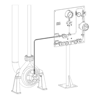
An experienced seal support system vendor like Swagelok takes the time to consult on-site, understand the process, evaluate the surrounding infrastructure—which is essential for plan upgrades or replacements—and ask about any problems you’ve had maintaining systems. With this information, our Field Engineers can develop the technical drawings and specificationsfor your API Plan 32.
Custom design and configuration may include:
- Flowmeter and transmitter to monitor flush flow and alert to unfavorable changes
- Thermowell tee, thermometer, with temperature transmitter using a thermowell pre-welded into tube fitting tee for ease of installation and maintenance
- Pressure gauges and transmitters to monitor flush pressure from the source
- Easily-accessible, easily maintained strainer or filter to prevent clogging caused by poor quality flush fluid
- Check valve to prevent process fluid from infiltrating flush fluid in the event of mechanical seal failure
The API Plan 32 customized to your specifications is built in our Fremont facility by certified technicians who follow the ISO 9001 quality standards. Swagelok’s local multi-million dollar inventory of top-quality parts and components help ensure your system is fabricated and thoroughly tested without delay. Our local experts are available to provide ongoing technical support, helping you avoid any headaches and ensuring you’re getting the optimum performance from your seal support system.
To find out more about how Swagelok Northern California can help you avoid headaches associated with API Plan 32 troubleshooting by providing expert consultation and Assembly Services, contact our team today by calling 510-933-6200.
 About Paul Lesnau | Sales Manager, Business Development Manager, and Field Engineer
Paul holds a B.S. in Mechanical Engineering from North Dakota State University. Before joining Swagelok Northern California, he was the West Coast Regional Sales Manager for an organization focused within the pneumatic and hydraulic industry where he supervised product distribution throughout the western United States, Canada, and Mexico. While in this role, he was able to help provide technical and application-specific expertise to customers and distribution to drive specifications.

")