Your first day on the job you got a tour of the refinery that you’re responsible for maintaining. It was probably overwhelming to see the complexity of the infrastructure. The leap from textbooks or trade school to the refinery is a big one—especially when it comes to centrifugal pumps.
In the Northern California refineries that I’ve consulted, you’ll find thousands of these pumps. Reliability is paramount. Knowledge of mechanical seals and seal support types can go a long way in helping you maintain these pumps, diagnose developing problems, and fix them before they lead to catastrophic failure and potential sanctions from regulatory agencies like Cal/OSHA or BAAQMD. API Standard 682 is the definitive source describing all the mechanical seal support types in detail, but few technicians have time to read through that document. Here, I’ve provided a condensed, yet detailed, summary of the mechanical seal support types—process side, between-seals, and atmospheric—that you’re likely to encounter in the petrochem refinery.
An Overview of Mechanical Seal Support Types
Seal support systems are paired to the specific process conditions and the mechanical seal. Often, however, process conditions do change over time, especially in older refineries, and the seal support system is overlooked. Without a seal support system that is properly selected, designed, and installed, you can see a shorter seal lifecycle, or worse. To maintain optimum seal reliability, you need to ensure that you have the right seal support system for the job.
Let’s take a look at your options.
Process Side Mechanical Seal Supports
A process side mechanical seal consists of two flat, highly-polished surfaces (rings) pressed together by a spring. Process fluid creates a film between these two surfaces to lubricate, absorb heat, and prevent the mechanical seal abrasion. Heat from rotation of the rings causes the film to vaporize from the high-pressure side to the low-pressure side and enter the atmosphere. For this reason single, process-side mechanical seals are used when process fluids pose no environmental risks.
Process side mechanical seal support systems circulate process fluids to or from the seal chamber to maintain the appropriate lubrication, pressure, and temperature, and prevent process fluid particulates from damaging seal faces. A simple way to categorize process side mechanical seal support types is: process fluid flush, cooled flush, cyclone separator, and external flush. Here are the different options for each:
|
Category
|
API Plan And Description
|
|
Process fluid flush
.png?width=106&name=image2%20(5).png)
API Plan 11 shown with some optional components.
|
API Plan 11 circulates process fluid from pump discharge to the seal chamber.
Use case: moderate temperatures, clean, non-polymerizing process fluids; applicable to both vertical and horizontal pumps
API Plan 12 circulates filtered process fluid using a Y strainer from pump discharge to the seal chamber.
Use case: slightly dirty, non-polymerizing process fluids; optional pressure gauges help monitor strainer condition
API Plan 13 circulates process fluid from the seal chamber to pump suction.
Use case: an alternative to Plan 11 when there is a low-pressure margin between discharge and seal chamber pressure; enables the seal chamber to be self-venting in horizontal pumps
API Plan 14 circulates process fluid from pump discharge to seal chamber, then back to pump suction.
Use case: light hydrocarbon processes to reduce seal chamber pressure
|
|
Cooled flush
.png?width=122&name=image5%20(2).png)
API Plan 21 shown with some optional components.
|
API Plan 21 circulates process fluid from pump discharge through a heat exchanger, then to the seal chamber.
Use case: improves temperature margin to reduce coking or polymerizing high-temperature applications, such as with a water temperature greater than 176°F (80ºC) and hot hydrocarbons
API Plan 22 circulates process fluid from pump discharge through a Y strainer and a heat exchanger then to the seal chamber to improve the temperature margin to reduce coking or polymerizing.
Use case: slightly dirty, high-temperature process liquids
API Plan 23 circulates process fluid, using a pumping ring, from the seal chamber to the heat exchanger, then back to the seal chamber. A throat bushing isolates the cooled seal chamber flush fluid from the hot process fluid
Use case: hot hydrocarbon processes and boiler feed water
|
|
Cyclone separator
.png?width=125&name=image2%20(5).png)
API Plan 31 shown with some optional components.
|
API Plan 31 circulates process fluid from pump discharge to a cyclone separator, then sends clean process fluid to the seal chamber and solids to pump suction. A throat bushing is typically installed.
Use case: process fluids with suspended solid at least twice the specific gravity of the process fluid
API Plan 41 is the same as API Plan 31, with the addition of a heat exchanger connected to the cyclone chamber clean flush outlet.
Use case: reduces process fluid coking or polymerizing
|
|
External flush
.png?width=125&name=image6%20(1).png)
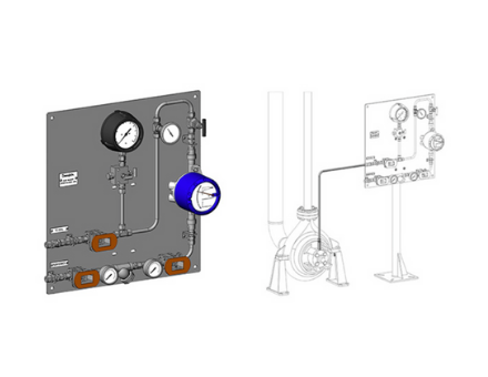
API Plan 32 Assembly and API Plan 32 Kit Panel shown with some optional components.
|
API Plan 32 uses an external source of clean, cool flush fluid such as plant water or nitrogen into the seal chamber to provide pressure greater than seal chamber pressure
Use case: dirty or contaminated, high-temperature, polymerizing, or oxidizing process fluids
|
Between/ Dual Seal Mechanical Seal Supports
A dual mechanical seal arrangement is comprised of a “primary” (inboard) seal and a “secondary” (outboard) seal. In comparison to single seals, dual mechanical seals provide superior protection against process fluid leakage into the atmosphere. Typical petrochem refinery applications include dirty, abrasive, hazardous, toxic, or polymerizing process fluids where leakage to the atmosphere is unacceptable.
Between, or dual, mechanical seal support systems deliver an unpressurized buffer or pressurized barrier fluid that can be either liquid or gas to lubricate the seal faces and remove heat from the seal chamber. Buffer fluids allow leakage of process fluid across the outboard seal into the buffer fluid, which can then be vented to flare. Barrier fluids leak across the inboard seal into the process fluid and must be chemically compatible with the process fluid. Here’s a rundown on each:
|
Category
|
API Plan And Description
|
|
Buffer fluids (unpressurized)
.png?width=147&name=image3%20(3).png)
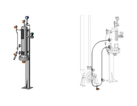
API Plan 52 Seal Pot Assembly and API Plan 52 Kit shown with some optional components.
|
API Plan 52 delivers buffer fluid from a reservoir to the outboard seal using a pumping ring.
Use case: light hydrocarbons, clean, non-polymerizing process fluid having vapor pressure higher than buffer fluid pressure.
API Plan 55 is a custom engineered system that circulates buffer fluid to and from the seal chamber using a pump located on an external reservoir. It provides cooling and lubrication to the outboard seal regardless of pump operation.
Use case: process fluids should be clean, non-polymerizing, with high vapor pressure or high-temperature, or fluids that insufficiently lubricate seal faces
API Plan 72 delivers buffer fluid, usually nitrogen, between the inboard and outboard seals while the coalescing filter removes any moisture and particulates present in nitrogen supply. Nitrogen dilutes process fluid leakage from the inboard seal and directs it to a collection system.
Use case: hydrocarbons prone to flashing
|
|
Barrier fluids (pressurized)
.png?width=144&name=image3%20(3).png)
API Plan 53A Assembly and API Plan 53A Kit shown with some optional components.
|
API Plan 53A circulates barrier fluid from an external reservoir to the outboard sealusing a pumping ring plant nitrogen is the usual source of pressurization to maintain at least 20psi above seal chamber pressure.
Use case: leakage to atmosphere is unacceptable; dirty, abrasive or polymerizing fluids with poor lubrication properties for inboard seal faces.
API Plan 53B is similar to Plan 53A with the pressurization source being a bladder accumulator
Use case: prevention of gas absorption into the barrier fluid, allowing higher operating pressure than Plan 53A
API Plan 53C is similar to Plan 53A with the pressurization source being a piston accumulator.
Use case: applications where the seal chamber pressure varies during pump operation because a sensing line connecting the seal chamber to the piston accumulator to maintain constant pressure
API Plan 54 is a custom-engineered system that circulates barrier fluid to and from the seal chamber using a pump located on an external reservoir. There are optional filters, coolers, and components to meet process requirements.
Use case: high pressurized plan reliability requirements for dual seals
API Plan 74 delivers barrier fluid, typically nitrogen, from an external source between the inboard and outboard seals. A coalescing filter removes any moisture and particulate present in plant nitrogen and allows a small amount of nitrogen to migrate into the process fluid
Use case: temperate, but toxic process fluids where leakage to atmosphere is unacceptable. Process fluid particulates that damage seal faces.
|
Atmospheric Mechanical Seal Supports
In certain process applications where a dual mechanical seal is not required, a single mechanical seal requires a pressureless quench to be delivered to the atmospheric side of a single seal in order to function effectively. The quench can be plant water, plant nitrogen, or steam. You have two plan options in this category:
|
Category
|
API Plan And Description
|
|
Quench
.png?width=146&name=image2%20(5).png)
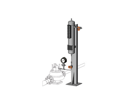
API Plan 62 Kit shown with some optional components.
|
API Plan 51 quenches the atmospheric side of a single seal from an external reservoir; prevents icing on the atmospheric side of the seal on vertical pumps.
Use case: clean, non-polymerizing process fluids
API Plan 62 quenches the atmospheric side of a single seal using steam, nitrogen, or clean plant water to prevent coking on seal faces.
Use case: hot hydrocarbon processes
|
Yes, that’s quite a bit of information, but I’m hopeful that this categorization of mechanical seal support types gives you a better understanding of the types of refinery applications where you can expect to see these systems employed. But don’t worry if you didn’t get it all this time around. When you find yourself needing to obtain parts, upgrade, or replace one of these mechanical seal support types, you can make the process easy with the help of a local mechanical seal support system vendor.
Swagelok Is Your Local Partner for Mechanical Seal Support Systems
.jpg?width=551&name=image8%20(1).jpg)
Swagelok has worked closely with refineries in the Northern California Bay Area counties for well over 50 years. Our experienced Field Engineers and certified technicians work from facilities right here in Northern California to provide field verification of your requirements as well as rapid delivery of seal support system assemblies, components, and parts, and ongoing technical support.
We’re ISO 9001 certified and our technicians fabricate and thoroughly test your systems prior to delivery. And to give you added confidence regarding the quality of our design and fabrication process, Swagelok’s Lifetime Warranty is the industry's best. From the perspective of location, experience, fabrication, and service, we provide the full spectrum of support.
To find out more about how Swagelok Northern California can help you determine the mechanical seal support types needed for your refinery processes by providing expert consultation and Assembly Services, contact our team today by calling 510-933-6200.


.jpg?width=1999&name=image7%20(1).jpg)