Any process industry that relies on centrifugal pumps to support its operations understands the importance of pump reliability. Although many pumps continue to use packing glands to prevent leaks of non-toxic or non-hazardous fluids, the majority of pumps employ mechanical seals to help ensure a high level of leak prevention. There is an astounding number of mechanical seals to fit specific pumping requirements. The type of fluid and its temperature, pump volume, and pumping pressure are key factors that guide the selection of the type of mechanical seal.
Equally important in maintaining the reliability of the centrifugal pumps are the auxiliary seal plans that maintain the proper conditions for mechanical seals. Auxiliary seal plans for centrifugal pumps provide critical lubrication and cooling for mechanical seals.
3 Categories of Auxiliary Seal Plans for Centrifugal Pumps
There are more than 30 different auxiliary seal plans as defined by the API 682 4th Edition. Each of these plans can have design variations to tailor the plan to the specific pumping requirements. The best way to think about these different seal plans and their variations is by grouping them into three categories—process side, between seal, and atmospheric side.
Process Side Auxiliary Plans
Process side auxiliary plans support a single mechanical seal to prevent centrifugal pump leakage. The process fluids are typically non-toxic. Process side auxiliary plans maintain the right seal chamber conditions by circulating process fluid through the seal chamber to provide cooling and lubrication to the mechanical seal. In comparison to the between seal and atmospheric plans, the process side plans are some of the simplest in design.
Circulate Process Fluid
API Plan 11 (Flush) takes process fluid from the pump’s discharge piping and circulates it to the seal chamber. If the pump has a vertical orientation, API Plan 13 (Reverse Flush) takes the process fluid from the seal chamber and pipes it to the suction side of the pump to vent seal chamber gases and reduce seal chamber pressure.
Remove Contaminants, Particulates, and Solids
API Plan 12 (Flush with Strainer) removes contaminants or particulates using a strainer to prevent damage to the mechanical seal. API Plan 31 (Flush with Cyclone Separator) uses a cyclone separator to remove solids from the process fluid. Fluid is taken from the pump discharge, routed through the cyclone separator, where the solids are removed and then routed to the pump suction. Clean flush fluid leaving the separator is routed to the seal chamber.
Cool Process Fluid
API Plan 14 (Flush) combines Plans 11 and 13 to provide higher cooling capacity without the need for a heat exchanger. API Plan 21 (Cooled Flush) adds a cooler to Plan 11 for better control of flush vapor margins. API Plan 22 (Cooled Flush with Strainer) adds a strainer to Plan 21 to deliver a cool, clean flush of process fluid to the seal chamber.
.jpg?width=200&name=Screenshot%202021-05-03%20074320%20(1).jpg)
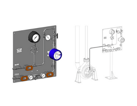
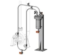
API Plan 23 (Recirculated Cooled Flush) (pictured above) uses a pumping ring located in the seal chamber to route process fluid to a cooler then return the cooled fluid to the seal chamber. API Plan 41 (Cooled Flush with Cyclone Separator) adds a heat exchanger to Plan 31 to deliver cool clean process fluid to the seal chamber.
Clean, External Flush When Process Fluid Is Not Suitable
API Plan 32 (External Flush) is used when the process fluid cannot be used to cool and lubricate the mechanical seal. Instead, a clean flush fluid (typically water, but can also be HVGO or HCGO) from an external source is delivered at pressure to the seal chamber. This plan depends on a close-clearance throat bushing in the seal chamber to ensure a higher pressure in the seal chamber and prevent process fluid from entering the seal chamber.
Between (Dual) Seal Auxiliary Plans
Between seal auxiliary plans for centrifugal pumps support dual mechanical seals that are needed to prevent leakage of hazardous or toxic fluids such as hydrocarbons. Dual
mechanical seals have an inboard seal and an outboard seal that prevent leakage of process fluid by creating a cavity between the two seals that is filled with fluid.
When the fluid delivered to the cavity is unpressurized, it forms a buffer between the process fluid and the atmosphere. When the fluid delivered to the cavity is pressurized, it forms a barrier between the process fluid and the atmosphere. The buffer and barrier fluids also lubricate the mechanical seals and remove frictional heat to maintain the required environment for the dual mechanical seals. Buffer and barrier fluids can be water, water/glycol, petroleum-based hydraulic and lubricating oils, synthetic hydraulic oils, diesel, kerosene, heat transfer fluids, and nitrogen. The buffer and barrier fluids must be compatible with process fluid because they invariably mix with process fluids.
Buffer Fluids
API Plan 52 circulates an unpressurized buffer fluid from a reservoir to the cavity between the inboard and outboard seals using a pumping ring in the seal chamber. This plan is often used with light hydrocarbons or fluids with high vapor pressure. The reservoir may optionally include cooling coils to remove heat from the circulating buffer fluid.
API Plan 55 is a custom-engineered system. It delivers cool, clean unpressurized buffer fluid to the cavity between the inboard and outboard seals using a pump located on an external reservoir. The plan can be configured with filters, coolers, and other instrumentation and components to meet process requirements.
API Plan 72 delivers a buffer gas (typically plant nitrogen) from an external source to the cavity between the inboard and outboard seals. The buffer gas pressure is no greater than 10 psi, allowing process fluid to leak across the inboard seal and swept to a collection system.
Barrier Fluids
The “53” plans—A, B, and C—circulate pressurized barrier fluid between a reservoir and the cavity between the dual seals in the seal chamber. Barrier fluid is intended to leak across the inboard seal face to lubricate the seal faces and pass into the process. A pumping ring is used to circulate barrier fluid between the seal chamber and reservoir, which may include cooling coils or use a heat exchanger to remove heat from the circulating barrier fluid. Each plan provides a different means of pressurizing the barrier fluid.
- API Plan 53A pressurizes the barrier fluid to at least 20 psi above the maximum seal chamber pressure using plant nitrogen.
- API Plan 53B uses a bladder to pressurize barrier fluid. The advantage of this plan is that it does not allow gas absorption into the barrier fluid which may allow for higher operating pressures than Plan 53A.
- API Plan 53C uses a piston accumulator to pressurize barrier fluid and is ideal for applications where the seal chamber pressure varies during pumping operations. A sensing line runs from the seal chamber to the piston accumulator to allow a constant pressure differential to be maintained.
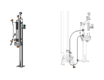
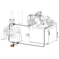
API Plan 54 (pictured below) is a custom-engineered system. It delivers a pressurized barrier fluid to the cavity between the inboard and outboard seals using a pump located on an external reservoir. This fluid is delivered at a pressure greater than the seal chamber pressure. The plan may include filters, coolers, and other instrumentation and components tailored to the needs of the process.
API Plan 74 supplies a pressurized barrier gas (typically, clean, dry plant nitrogen) from an external source to the cavity between the dual seals at a pressure at least 25 psi above the seal chamber maximum pressure. This plan provides a high level of protection against process leakage into the atmosphere. A flow transmitter added to the gas supply alerts to leakage in the event of a seal failure.
Atmospheric Side Auxiliary Plans
Atmospheric side mechanical seals in pumps processing cold hydrocarbon services can experience icing which is caused by condensation and freezing of atmospheric humidity on the seal. If the humidity penetrates and freezes within the mechanical seal mechanism pump reliability can significantly decline. Plants controlling crude oil can end up with coking, as well.
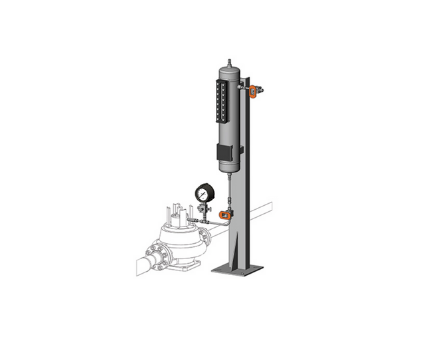
API Plan 51 (pictured below) is the solution to this problem and intended for use in vertical pumps. The plan dispenses a dead-ended blanket of fluid from a reservoir to the gland plate’s quench connection to prevent icing on the mechanical seal.
When a mechanical seal (single or the outboard of a dual seal) in a centrifugal pump processing high-temperature hydrocarbons is exposed to the atmosphere it can experience coking. This is caused by oxidation or chemical decomposition, resulting in residues that build up on the seal. Abrasion caused by these residues will quickly degrade the seal face.
API Plan 62 is the solution for this problem. It delivers an external quench fluid (typically steam, but nitrogen or water is also used) to the atmospheric side of the seal. This cools and cleans the seal faces and creates a barrier between seal faces and the atmosphere to prevent crystallization on the atmospheric side of the seal faces.
Work With Local Experts To Choose the Best Auxiliary Plan
.jpg?width=300&name=Screenshot%202021-05-03%20074022%20(1).jpg)
With the number of auxiliary seal plans for centrifugal pumps and their various configurations, choosing the correct one can be overwhelming unless you have years of experience in designing and fabricating these systems. You’ll save yourself time and money when you work with local seal support system vendors who bring years of experience in assessing process requirements and recommending the right auxiliary seal plan for centrifugal pumping processes. Field engineers conduct onsite assessments to understand your process and pumping conditions, fluid compatibility issues, existing infrastructure, and installation challenges. That information is vital in helping you choose the best auxiliary plans.
Swagelok brings more than five decades of industry experience to help you choose the best seal auxiliary plans for your centrifugal pumps. We can design, fabricate, and thoroughly test the auxiliary seal plans that best meet your process, pump, and mechanical seal requirements. Swagelok has been meeting the seal support system needs for process industries throughout Northern California. We offer a wide range of auxiliary seal support plans, available as kits or assemblies.
To find out more about how Swagelok Northern California can help you choose the best auxiliary seal plan centrifugal pumps in your organization by providing expert consultation and Assembly Services, contact our team today by calling 510-933-6200.


.jpg?width=1000&name=shutterstock_399739879%20(1).jpg)