Menu
- Engineering Services
- Product Lines
- Resources
- About
- Shop


.jpg?width=544&name=shutterstock_609092369%20(1).jpg)
Seal support systems are vital to the reliable functioning of the thousands of pumps that keep a refinery running around the clock. When they are properly designed, installed, and maintained, the seal support systems help ensure pump reliability and maximize the pump life by maintaining the optimum seal chamber conditions. In Northern California, pump reliability takes on an added dimension—environmental compliance. Any leakage of hydrocarbons could result in sanctions from the California Division of Occupational Safety and Health (Cal/OSHA) or Bay Area Air Quality Management District (BAAQMD).
If you’re new to API plans, you’ll quickly realize that the range of options available in API seal flush plans reflects the range and complexity of the various pumping processes and conditions across a refinery. Choosing the right API seal flush plan is a critical step in ensuring pump reliability. In my years of experience in working with process engineers and maintenance teams at Northern California refineries, we’ve always achieved better outcomes when I have the opportunity for on-site analysis of pumping processes and can advise them on the latest advancements and configuration options available.
.png?width=150&name=image6%20(2).png)
-1.png?width=150&name=image3%20(4)-1.png)
Process Side Plans Between Seal Plans Atmospheric Side Plans
The tables below provide an overview of the three standard categories of API seal flush plans—process side, between seals, and atmospheric. It’s not a comprehensive list of all API plans, but I hope they provide enough information to help you understand the range of options available in each category and take the first steps in matching plans with your specific pumping processes.
Description: Process side API seal flush plans use a single mechanical seal to prevent pump (process) fluid from leaking. In this arrangement, the process fluid is the lubricant. It provides a thin film between the seal faces to reduce friction and absorb heat. In doing this, the pressurized process fluid “leaks” across the seal faces and returns to the process flow.
Use cases: Clean, non‐polymerizing process fluids that pose little or no environmental risk.
|
API Seal Flush Plan |
Plan Characteristics |
|
Plan 11 Flush |
Recirculates process fluid from pump discharge to the mechanical seal then returns fluid to the process via the pump seal chamber |
|
Plan 12 Flush with Strainer |
Includes a strainer/filter positioned before the flow control orifice to remove process fluid particulates and prevent clogging; Optional pressure gauges alert to flow problems |
|
Plan 13 Flush from Chamber to Suction |
Recirculates process fluid from the seal chamber back to the pump suction; Typically used for vertical pumps |
|
Plan 14 Flush (combines plans 11 & 13) |
Recirculates process fluid from pump discharge to the seal chamber, then from the seal chamber to pump suction |
|
Plan 21 Cooled Flush |
Recirculates process fluid from pump discharge through a cooler, then to the seal chamber; Preferred for viscous process fluids that could clog seal flush cooler |
|
Plan 22 Cooled Flush with Strainer |
Includes a strainer/filter positioned before the flow control orifice to remove process fluid particulates and prevent clogging; Optional pressure gauges alert to flow problems |
|
Plan 23 Cooled Flush Recirculated through Seal Chamber |
Recirculates process fluid from the seal chamber through a cooler, then back into the seal chamber using a pumping ring; By continually recirculating seal chamber fluid through the seal flush cooler, it provides greater cooling capacity compared to Plan 21 |
|
Plan 31 Flush with Cyclone Separator |
Recirculates process fluid from pump discharge through a cyclone separator, sending clean process fluid to the seal chamber and particulates back to pump suction; For optimum performance, particulates should have a specific gravity twice the process fluid |
|
Plan 32 External Flush |
Delivers clean or cool flush fluid to the seal chamber from an external source; Employs a close-clearance throat bushing to ensure seal chamber higher pressure; Because flush fluid will migrate past the bushing it must be chemically compatible with process fluid |
|
Plan 41 Cooled Flush with Cyclone Separator |
Recirculates process fluid from pump discharge through a cyclone separator, sending clean process fluid to the seal chamber and particulates back to pump suction; Particulates should have a specific gravity twice the process fluid |
Each of these API seal flush plans has options to help tailor the plan to the requirements of the specific pumping process. Instrumentation such as temperature, pressure, and flow gauges help monitor system performance. If you’re not using process fluid to lubricate the mechanical seal, flush fluids can be water, water/glycol, or mineral- or synthetic-based hydraulic and lubricating oils. Cooling capacity needs to be carefully calculated based on process fluid temperature, pressure, and mechanical seal type. When you’re faced with choosing among these options, the guidance of an experienced, local seal support system vendor is critical. Well-informed design decisions are the foundation for long-term reliability.
Description: The majority of refinery processes deal with hydrocarbons. In comparison to process side API seal flush plans, between seal plans provide a higher degree of protection against leakage. As a result, between seal plans (or dual mechanical seals) are used in the majority of refinery pumping applications.
These API seal flush plans deliver a barrier (pressurized) or buffer (unpressurized) fluid delivered from an external source to the space between the inboard and outboard seals. Barrier fluids can be a water/glycol mix, or mineral- or synthetic-based hydraulic and lubricating oils.
Barrier fluids are delivered at a pressure 15 to 30 PSIG (1 to 2 BAR) higher than the process fluid pressure. Buffer fluids are delivered at a pressure lower than the process fluid pressure. As a result, barrier fluids will mix with the process fluid and process fluids will mix with buffer fluids. Barrier and buffer fluids must be chemically compatible with process fluids.
Use cases: Toxic, hazardous, polymerizing, abrasive fluids, and light hydrocarbons. Avoiding leakage of expensive process fluids. Providing the proper lubrication when the process fluid (gases, viscous fluids, slurries, polymerizing fluids) lacks the lubrication properties.
|
API Seal Flush Plan |
Plan Characteristics |
|
Plan 52 Buffer Fluid Seal Pot |
Delivers fluid from an external reservoir at a lower pressure than the process fluid pressure; An internal pumping ring circulates the buffer fluid; Optional cooling coils can be incorporated into the buffer fluid reservoir |
|
Plan 53A Barrier Fluid Seal Pot Pressurized by Nitrogen |
Delivers fluid from plant nitrogen supply at a higher pressure than the process fluid pressure; An internal pumping ring circulates the nitrogen barrier fluid |
|
Plan 53B Barrier Fluid Pressurized by Bladder Accumulator |
Uses a pressurized bladder accumulator to isolate pressurized gas from barrier fluid and delivers clean barrier fluid between the inboard and outboard seals at a pressure higher than the process fluid pressure; An internal pumping ring circulates the nitrogen barrier fluid; Bladder prohibits gas absorption into the barrier fluid and facilitates higher operating pressures than Plan 53A |
|
Plan 53C Barrier Fluid Pressurized by Piston Accumulator |
Preferred for applications where the seal chamber pressure varies during pump operation; Uses a sensing line from the seal chamber into the piston accumulator to deliver barrier fluid from a reservoir at a constant, but higher pressure than the process fluid pressure; An internal pumping ring circulates the barrier fluid |
|
Plan 54 Barrier Fluid Pressurized by External System |
Delivers clean fluid at a higher pressure than the process fluid using a pump located in the external reservoir |
|
Plan 55 Buffer Fluid Circulated by External System |
Delivers clean fluid using a pump located in the external reservoir at a lower pressure than the process fluid |
|
Plan 72 Buffer Gas |
Delivers buffer gas (typically plant nitrogen) from an external source to the seal chamber at a lower pressure than the process pressure; Uses a coalescing filter to remove any moisture and particulate present in the plant nitrogen supply; Any process fluid vaporizing across the inboard seal is then swept into a closed collection system |
|
Plan 74 Barrier Gas |
Delivers barrier gas (typically plant nitrogen) from an external source to the seal chamber at a higher pressure than the process pressure; Uses a coalescing filter to remove any moisture and particulate present in the plant nitrogen supply; Allows a small amount of nitrogen to leak into the process fluid |
.png?width=200&name=image7%20(2).png)
These plans also can also have a significant number of design options. Plans 54 and 55 lend themselves to a high degree of customization regarding reservoir volume, pump, filters, coolers, and instrumentations. These plans can also be configured to support multiple pumps with similar pumping characteristics. Plan 72 has the option of adding a condensing or non-condensing leakage collection system. For each of these, determining the proper pressure is one of the most critical factors regarding system performance.
If you’re making an investment in a new or upgraded seal support system, it’s well worth the time to work with an experienced Field Engineer who understands the importance of configuring the options for the specific pumping process.
Description: In comparison to the range of options in the above API seal flush plan categories, atmospheric side plans are much simpler. Their purpose is to provide a non-pressurized cooling flush to a mechanical seal's faces on the atmosphere side to prevent or remove solid formations—crystallization, icing, and coking. Water, steam, and nitrogen are the typical flush fluids.
A quench improves atmospheric seal performance by absorbing or removing any process fluid leakage, preventing process fluid from being exposed to the atmosphere, and cooling or heating (relative to the process fluid temperature) to prevent the formation of solids proximate to the mechanical seal.
Use cases:
|
API Seal Flush Plan |
Plan Characteristics |
|
Plan 51 Quench from Reservoir |
Delivers clean flush fluid from an external reservoir to the atmospheric side of a single seal preventing icing at ambient temperatures on the atmospheric side; Used for vertical pump applications |
|
Plan 62 Quench from External Source |
Delivers a low rate (2 to 4 PSI) of quench fluid (nitrogen, water, steam) from an external source to the atmosphere side of the seal. Typically uses a throttle bushing for containment. |
Each of the atmospheric side plans has an option to collect condensing process fluid leakage into a reservoir. In the event of excessive leakage, a level transmitter on the reservoir triggers an alarm.
The proper design of your flush plan is the biggest factor in ensuring long-term performance and reliability. You may have the in-house expertise to determine the appropriate API flush plans for the various pumps in a new installation or upgrades of existing pumps, but your outcomes will improve if you engage the service of an experienced, local partner. In working with process engineers for over the years, I can tell you first-hand that you’ll:
An experienced API seal flush plan partner has Field Engineers to evaluate each process and pumping conditions, fluid compatibility issues, and infrastructure considerations (on-site or virtually) to help determine plan requirements.
-1.png?width=470&name=image5%20(2)-1.png)
Swagelok has decades of expertise in helping refineries determine the proper API seal flush plans. We can design, fabricate, and thoroughly test the API seal plans prior to delivery. For over 50 years, Swagelok has been meeting the seal support needs of refineries in Northern California. We offer a complete range of API seal flush plans, available as kits or assemblies.
As a local partner, we understand the unique Bay Area challenges. Upgrades, working around infrastructure limitations, process changes—we’ve addressed all of them. And, we welcome the opportunity to work with you.
To learn how Swagelok Northen California can assist you in choosing API seal flush plans that are right for your process needs by providing expert consultation, design, and fabrication, contact our team today by calling 510-933-6200.
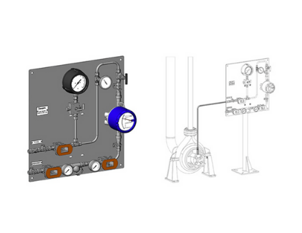
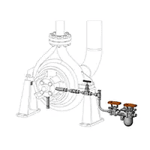
View process side plans including the API Plan 32 External Flush Assembly shown above.
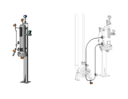
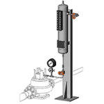
View 11 between-seal plans, including the Plan 52 Plan 52 Buffer Fluid Seal Pot shown above.
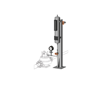
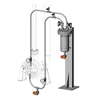
Click to view five plans, including the API Plan 51 Quench from Reservoir shown above.
We know it’s mission critical. You need a mechanical seal support system assembled and delivered. ASAP.
We understand the criticality of mechanical seal support replacement services when your refinery is running 24/7/365.