


/Digital%20montage%20(1).jpg?width=1920&name=Digital%20montage%20(1).jpg "Digital montage (1)")
by Morgan Zealear, on 4/15/21 8:45 AM
Pumping processes involving toxic or hazardous fluids that can’t risk leakage because of stringent environmental regulations require a double mechanical seal. Compared to a single mechanical seal, a double seal gives you significantly greater protection against leaks. With a double mechanical seal, you have an arrangement of two mechanical seals (a primary or inboard seal and a secondary or outboard seal) in series—back-to-back, tandem, or face-to-face. Each seal has a rotating (R) surface and a stationary (S) seal surface. These seals can be arranged in one of three patterns.
In a back-to-back arrangement, the stationary seal faces are positioned back-to-back with the rotating seal faces on the outside. The back-to-back arrangement is easy to install and used for many general pumping applications.
The tandem arrangement has the two pairs of seals mounted with the same orientation. This arrangement is preferred for toxic or hazardous applications because the outboard seal provides full pressure back-up, allowing the outboard seal to back up in the event of an inboard seal failure.
In the face-to-face arrangement, the rotating seal faces share a common stationary seal face. This arrangement is useful when equipment space is too constrained to permit back-to-back or tandem seal arrangements.
Two Basic Mechanical Seal Designs: Pressurized or Unpressurized
The American Petroleum Institute (API) Standard 682 classifies double mechanical seals into two configurations—pressurized and unpressurized. The pressurized arrangement has a barrier fluid delivered to the double mechanical seal by a seal support system. The barrier fluid is delivered at a higher pressure than the process fluid and must be chemically compatible with the process fluid as it will lubricate the inboard seal faces and mix with the process fluid. The unpressurized arrangement has a buffer fluid delivered to the double mechanical seal by a seal support system. The buffer fluid is delivered at a lower pressure than the process fluid.
The barrier and buffer fluids you use can be liquid or gas. They provide lubrication and help maintain the required operating temperature of the seal faces. The typical choices are water and water/glycol mixtures, low-viscosity petroleum or synthetic oils, kerosene, diesel, and nitrogen.
Comparing Two API Plans for Double Mechanical Seals
To gain a better understanding of the differences between the uses of barrier and buffer fluids, let’s look at two common API plans for double mechanical seals—API Plan 52 Buffer Fluid Seal Pot and API Plan 53A Barrier Fluid Seal Pot Pressurized by Nitrogen.
API Plan 52 Buffer Fluid Seal Pot
API Plan 52 takes buffer (unpressurized) fluid from a reservoir (seal pot), delivers it to the seal chamber, circulates it between the inboard and outboard seals using a pumping ring located driven by shaft rotation, then returns the fluid to the reservoir. In the event of an inboard seal failure, process fluid leaks into the seal chamber. When that occurs an increase in buffer fluid pressure and/or level alerts operators to the problem. The outboard seal, however, contains leakage until maintenance can replace the damaged seal.
-1.png?width=360&name=image2%20(3)-1.png)
API Plan 52 Showing Flow And Design Options
This plan can include cooling coils in the reservoir to maintain the required buffer fluid temperature, visual or mechanical fluid level indicators, pressure and level transmitters, and connection to a collection system and buffer fluid replenishment source.
The overall design of this API plan for a double mechanical seal is relatively simple in comparison to other plans. Design decisions involving tubing size, length, geometry, type (carbon vs stainless steel), buffer fluid type, and volume of the buffer fluid reservoir are critical in maintaining the proper operating environment for the double seal. If you don’t have this expertise in-house, work with an experienced, local seal support system vendor to ensure the API Plan 52 is designed to meet your specific pumping requirements.
API Plan 53A Barrier Fluid Seal Pot Pressurized by Nitrogen
API Plan 53A is conceptually similar to API Plan 52 with the difference that the fluid being circulated between the double mechanical seals is under pressure. A pumping ring is used to circulate the fluid. The reservoir that contains the barrier fluid is pressurized by plant nitrogen. Reservoir pressure should be set a minimum of 20 to 25 psi (1.4 to 1.73 bar) above the maximum seal chamber pressure, allowing the barrier fluid to leak (and lubricate) across the inboard seal faces into the process fluid. For this reason, the barrier fluid must be chemically compatible with the process fluid.
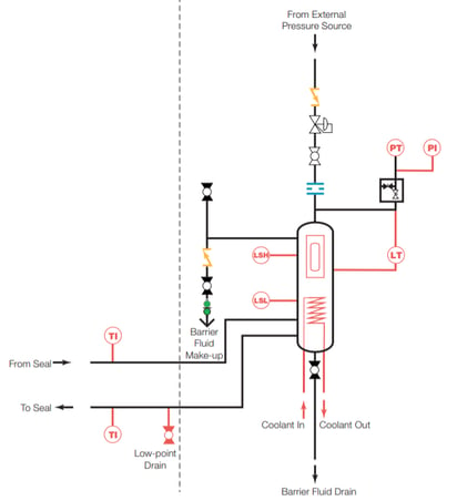
API Plan 53A Showing Flow And Design Options
Because barrier fluid is depleted as it moves across the inboard seal faces, it needs to be replenished. This can be done manually or automatically by way of a system that serves multiple pumps. API Plan 53A design options include reservoir type and volume, cooling coils, fluid level and pressure indicators, and transmitters to alert to level or pressure changes that indicate seal failure.
Choosing an API Plan for a Double Mechanical Seal
When you choose an API plan for a double mechanical seal, your primary decision is between a buffer or barrier plan. I’ve highlighted two of the API plans for double mechanical seals above to show the basic differences. There are multiple API plans for double mechanical seals to choose from—pressurization from bladder or piston accumulators, plant nitrogen delivered directly to the seal chamber, and custom-engineered external systems. Your choice will be determined by the process fluid and pumping conditions and the type of double mechanical seal your vendor recommends.
With this information in hand, it’s best to work with an experienced local seal support system vendor. They’ll be able to meet with you on-site to review the specifications for the pumping process, the pump, and the double mechanical seal. They’ll evaluate your existing infrastructure and its influence on seal support system design. Based on this information, they’ll then design the seal support system to meet the specific pumping requirements.
If you work with a global vendor like Swagelok, based on the design, we can quickly assemble and thoroughly test the API plan at our local facilities prior to delivery. We’re also conveniently available for follow-up consultations, on-site, remotely, or by way of a quick phone call.
Swagelok: Global Experience and Local Expertise
For well over 50 years, Swagelok has worked closely with Northern California process industries to confidently choose the right API plans for pumping needs. Our locally based Field Engineers and certified technicians provide field verification of your seal support requirements, designs based on best practices gained from global experience.
To find out more about how Swagelok Northern California can help you choose the right API plan for double mechanical seals, as well as process and atmospheric side seals, contact our team today by calling 510-933-6200.
 Morgan Zealear | Product Engineer – Assembly Services
Morgan holds a B.S. in Mechanical Engineering from the University of California at Santa Barbara. He is certified in Section IX, Grab Sample Panel Configuration, and Mechanical Efficiency Program Specification (API 682). He is also well-versed in B31.3 Process Piping Code. Before joining Swagelok Northern California, he was a Manufacturing Engineer at Sierra Instruments, primarily focused on capillary thermal meters for the semiconductor industry (ASML).

")