
.webp?width=210&height=70&name=StickyLogo%20(5).webp "Swagelok Northern California home page")
Share this
by Jeff Hopkins on 7/22/15 7:00 AM
Flash steam recovery for non-modulating applications, a flash tank
We've written previously about flash steam recovery in modulating applications. Today we tackle the same general topic of steam recovery, but for non-modulating applications.
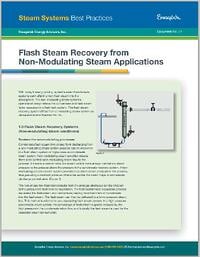
"Non-modulating" means there is no control valve modulating steam flow to the process. The system provides a constant steam pressure, thus providing a constant pressure differential across the steam traps or condensate discharge control valve.
Examples of non-modulating steam processes include steam tracing, drip leg steam traps, unit heaters, process heaters, reboilers and corrugators.
The non-modulating steam system’s operational design allows the condensate and flash steam to be recovered in a flash tank system. The flash tank is used to:
• Separate condensate and flash steam
• Control the flashing process
• Allow enough space for flash steam to be released
• Reduce the velocities of the flash steam to ensure no condensate carryover with the flash steam
Decisions, decisions
Now come the crucial decisions. How big should the flash tank be for a particular system?
Should the tank be mounted vertically or horizontally? What outlet velocities are within an acceptable range? Can your particular setup use a cascade steam system for recovery, or does it need a thermocompressing system?
To reach those answers, you'll need to make some calculations. The first one is to figure out the amount of condensate entering the flash tank. That will be the sum of the steam-consuming capacity of all equipment discharging into the condensate return line that is going to the flash tank. This could be only one component or multiple components.
Next determine the process pressure and flash tank pressure.
Then calculate the condensate that flashes to steam. From there you can size the steam space.
Where can you find the formulas for those calculations? Click here to read the steam system best practice: Flash Steam Recovery from Non-Modulating Steam Applications and download a free, illustrated, five-page PDF of best practices related to flash steam recovery from non-modulating applications with steps to designing a flash tank and detailed examples.
Additional Resources
 |
 |
|
| Plan Your Steam System Success eBook | Steam Systems Engineer Site Visit | |