Share this
How a Seal Support System Aids Recovery of Hydrocarbons
by Morgan Zealear on 4/22/21 8:45 AM
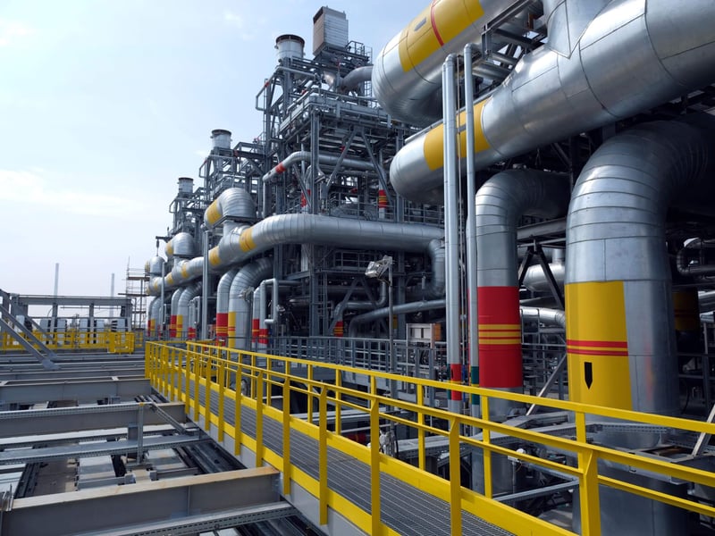
Refinery processes involving light hydrocarbons and high vapor pressure fluids present challenges in ensuring that that they remain safely contained within the systems, piping, and pumps involved in the process. Centrifugal pumps that drive these processes present critical points of potential leakage. Dual mechanical seals and seal support systems that deliver buffer or barrier fluid to the seal are the methods of choice for maintaining pump integrity and avoiding any leakage to the atmosphere.
API Plan 72 is often chosen to supply a clean, dry buffer gas (typically nitrogen) between the dual seals at a pressure lower than the process pressure. A pressure regulator sets the nitrogen pressure, which is usually no higher than 10 psi (0.68 bar) as it enters the seal chamber. This allows minor amounts of process fluid to leak across the inboard seal into the buffer gas. The nitrogen dilutes process leakage from the inboard seal and sweeps it to a vapor recovery collection system.
If the leakage is significant, or any loss of process fluid equates to lost revenue or environmental pollution, the refinery may choose to return the leakage captured in the vapor recovery system to the process rather than vent it to flare. API Plan 76 is often recommended as the seal support system for the recovery of non-condensing leakage.
API Plan 76: Seal Support System for Recovery
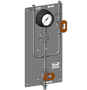
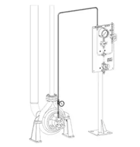
API Plan 76 is a non-condensing leakage collection system. It collects leakage from the inboard seal in centrifugal pumps where process fluid leakage does not condense between the seals at ambient temperatures. This vaporous leakage from the inboard seal exits through the containment seal vent port located at the top of the outboard seal gland. The orifice is sized to create the necessary back-pressure for a pressure transmitter to send an alarm in the event of a seal failure. Vapor is then transported to a recovery system. This seal support system for recovery of leakage ensures virtually no process emissions from the outboard containment seal in a dual seal arrangement.
|
API Plan 76 panel |
API Plan 76 installed on pump |
Designing a Seal Support System for Recovery Optimization
Although the functional designs of API Plan 72 and API Plan 76 are standardized, not specified, there’s good reason to work with an experienced fluid systems engineer when implementing a new system or updating an existing seal system. They’ll evaluate the specific process conditions and consider factors that influence system design.
- Design decisions for API Plan 72 may include the type of buffer gas and source, buffer gas pressure, a coalescing filter to remove moisture or particulates, a flowmeter, and possibly a pressure gauge or transmitter to monitor buffer gas.
- Design decisions for API Plan 76 will likely include tubing diameter to transport vapor to the vapor recovery system, a flow control orifice size to generate required back pressure, and a pressure gauge and/or a pressure transmitter with an alarm to alert when the pressure in the vapor collection system increases—indicating unacceptable leakage across the inboard seal.
These design decisions are critical to the proper functioning of the mechanical seal support system and its ability to effectively recover hydrocarbon leakage into the seal chamber.
Seal Support Systems for Recovery: A Combined Solution
Because API Plans 72 and 76 are frequently deployed together, the systems can be combined into a single panel to simplify installation, management, and maintenance. The combined panel controls the delivery of buffer gas to the dual mechanical seal, as well as collects process fluid leakage into a recovery system.
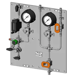
Panel with combined API Plans 72 and 76 |
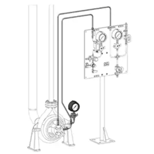
API Plans 72 and 76 connected to pump |
Swagelok Expertise Aids Hydrocarbon Recovery
If any of your currently installed mechanical seal support systems are underperforming in their ability to capture and recover hydrocarbons because of changes to process conditions, aging components, maintenance difficulties, or poor design and implementation, Swagelok will work with you to understand the issues and recommend solutions that eliminate those problems. Our local Field Engineers will conduct an onsite analysis of the pumping process, identify factors that undermine performance, and recommend components, design changes, upgrades, or even replace seal support systems, if necessary.
For more than 50 years, Swagelok has been serving the needs of the chemical and petroleum industries in Northern California. Swagelok maintains an extensive inventory of top-quality fluid system components in our Bay Area facilities. Our local technicians can quickly build and test any assemblies or complete seal support systems prior to delivery. When you work with Swagelok, you benefit from our refinery experience, the convenience of local support, and the backing of worldwide Swagelok industry expertise.
To find out more about how Swagelok Northern California is helping refineries design and deploy seal support systems to aid hydrocarbon recovery, by providing expert consultation and Assembly Services, contact our team today by calling 510-933-6200.
 Morgan Zealear | Product Engineer – Assembly Services
Morgan holds a B.S. in Mechanical Engineering from the University of California at Santa Barbara. He is certified in Section IX, Grab Sample Panel Configuration, and Mechanical Efficiency Program Specification (API 682). He is also well-versed in B31.3 Process Piping Code. Before joining Swagelok Northern California, he was a Manufacturing Engineer at Sierra Instruments, primarily focused on capillary thermal meters for the semiconductor industry (ASML).
Share this
- Archive (465)
- Assembly Services (207)
- About (100)
- Seal Support Systems (96)
- Best Practices (88)
- Training Services (74)
- Fittings (51)
- Semiconductor Applications (49)
- Hoses and Flexible Tubing (47)
- Regulators (44)
- Tubing (42)
- Grab Sampling Systems (32)
- Sampling Systems (32)
- Gas Systems (30)
- Services (30)
- Downloads (29)
- Valves (24)
- Application Support (18)
- Orbital Welding (17)
- Case Studies (13)
- Steam Systems (13)
- Frequently Asked Questions (12)
- Tools (12)
- Measurement Devices (7)
- Subsystems (6)
- Thermal Management (6)
- September 2023 (1)
- August 2023 (2)
- June 2023 (1)
- March 2023 (3)
- February 2023 (3)
- January 2023 (4)
- December 2022 (4)
- November 2022 (4)
- October 2022 (4)
- September 2022 (1)
- August 2022 (3)
- July 2022 (2)
- June 2022 (4)
- May 2022 (1)
- April 2022 (2)
- March 2022 (1)
- February 2022 (2)
- January 2022 (3)
- December 2021 (1)
- November 2021 (6)
- October 2021 (6)
- September 2021 (8)
- August 2021 (4)
- July 2021 (3)
- June 2021 (6)
- May 2021 (6)
- April 2021 (7)
- March 2021 (5)
- February 2021 (4)
- January 2021 (6)
- December 2020 (5)
- November 2020 (6)
- October 2020 (6)
- September 2020 (8)
- August 2020 (7)
- July 2020 (8)
- June 2020 (8)
- May 2020 (6)
- April 2020 (9)
- March 2020 (7)
- February 2020 (10)
- January 2020 (21)
- December 2019 (23)
- November 2019 (21)
- October 2019 (22)
- September 2019 (21)
- August 2019 (22)
- July 2019 (23)
- June 2019 (20)
- May 2019 (23)
- April 2019 (22)
- March 2019 (21)
- February 2019 (20)
- January 2019 (21)
- December 2018 (14)
- November 2018 (19)
- October 2018 (23)
- September 2018 (17)
- August 2018 (29)
- July 2018 (11)
- June 2018 (6)
- May 2018 (5)
- April 2018 (4)
- March 2018 (5)
- February 2018 (3)
- January 2018 (3)
- December 2017 (2)
- November 2017 (4)
- October 2017 (3)
- September 2017 (2)
- August 2017 (6)
- July 2017 (4)
- June 2017 (4)
- May 2017 (4)
- April 2017 (3)
- March 2017 (4)
- February 2017 (3)
- January 2017 (3)
- December 2016 (3)
- November 2016 (3)
- October 2016 (3)
- September 2016 (5)
- August 2016 (5)
- July 2016 (4)
- June 2016 (5)
- May 2016 (3)
- April 2016 (4)
- March 2016 (5)
- February 2016 (11)
- January 2016 (1)
- December 2015 (3)
- November 2015 (4)
- October 2015 (3)
- September 2015 (4)
- August 2015 (4)
- July 2015 (8)
- June 2015 (5)
- May 2015 (3)
- April 2015 (4)
- March 2015 (4)
- February 2015 (3)
- January 2015 (4)
- December 2014 (2)
- November 2014 (3)
- October 2014 (4)
- September 2014 (4)
- August 2014 (4)
- July 2014 (5)
- June 2014 (4)
- May 2014 (4)
- April 2014 (5)
- March 2014 (4)
- February 2014 (3)
- January 2014 (4)
- December 2013 (5)
- November 2013 (3)
- October 2013 (4)
- September 2013 (3)
- August 2013 (5)
- July 2013 (5)
- June 2013 (5)
- May 2013 (3)
- April 2013 (6)
- March 2013 (4)
- February 2013 (4)
- January 2013 (8)
- December 2012 (4)
- November 2012 (6)
- October 2012 (6)
- September 2012 (4)
- August 2012 (4)
- July 2012 (4)
- June 2012 (4)

.webp?width=210&height=70&name=StickyLogo%20(5).webp)
