
.webp?width=210&height=70&name=StickyLogo%20(5).webp "Swagelok Northern California home page")
Share this
by Paul Lesnau on 12/8/20 8:45 AM
.jpg?width=901&name=shutterstock_1147243691%20(1).jpg)
When you consider the variety of mechanical seal designs, there are significantly more wet mechanical seal designs than dry gas seal designs. But dry gas seals play a critical role in many petrochemical processes. It’s unlikely your undergraduate or technical school program devoted significant time to dry gas seals and their support systems, so I’ve provided a quick overview of the basics to familiarize you with their capabilities. I’ve also included some details about one of the most common API plans for dry gas seals—API Plan 74—to illustrate a practical application of the technology.
Dry Gas Seals: How They Work
Dry gas seals have non-contacting mechanical faces—a rotating ring and stationary ring. When operating, the rotating ring which has machined-in channels generates a fluid-dynamic lifting force that creates a minute gap between the two rings. Depending on the pressure of the gas being delivered to the seal chamber by the seal support system, the gas or the process fluid migrates across the seal faces. Dry gas seals are typically installed in centrifugal compressors or pumps used in petrochemical processing and gas transmission. Because dry gas seals are non-contacting, their useful life can far exceed the life of wet mechanical seals.
Dry Gas Seal Support Systems: Buffer and Barrier Gases
Dry gas seals need a supply of dry gas to maintain the required seal chamber environment. For compressors, the source is the compressor discharge which is filtered and delivered to the seal chamber at the correct pressure and flow by the seal support system. For centrifugal pumps, it’s usually plant nitrogen delivered at the proper pressure and flow by the seal support system.
When dry gas is delivered to the seal chamber at a pressure lower than the process fluid pressure, it’s called a buffer gas. At that pressure, process fluid can vaporize across the seal faces, enter the seal chamber, and be swept to a collection system or sent to flare. When dry gas is delivered to the seal chamber at a pressure above the process fluid pressure, it’s called a barrier gas because it won’t allow process fluid to vaporize across the seal face into the seal chamber.
Let’s take a look at one of the most common API plans for dry gas seals to get a better idea of how dry gas seals and their support systems work together.
API Plan 74 for Dry Gas Seals
API Plan 74 delivers pressurized barrier gas, usually from the plant nitrogen supply, to a dual or tandem seal arrangement. The dual seal arrangement—a combination of an inboard seal face pair and an outboard seal face pair—provides a high level of reliability against leakage of hazardous or toxic fluids.
To ensure clean, dry gas is delivered, the seal support panel contains a coalescing filter to remove any moisture or particulates that might be present in the plant nitrogen supply. The absence of contaminants or particulates in the gas contributes to seal reliability.
The pressure regulator on the panel is set to supply nitrogen at least 25 psi (1.7 bar) above the seal chamber pressure. As a result of the pressure, a small amount of nitrogen will migrate through the inboard seal into the process fluid. A flow transmitter located on the nitrogen supply can alert to an increase in nitrogen use which usually indicates a seal failure.
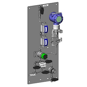
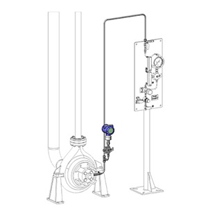
API Plan 74 panel configured with coalescing filter, flowmeter, and pressure regulator and shown delivering barrier gas to a dual mechanical seal arrangement in a light hydrocarbon pumping process.
API Plan for Dry Gas Seals Use Cases
API Plan 74’s capability to deliver barrier gas to a dry gas dual mechanical seal arrangement provides a high level of reliability against leakage into the atmosphere. Because of these capabilities API Plan 74 is appropriate for pumps or compressors used for:
- Process fluids containing solids or particulates that would ruin seal faces
- Toxic or hazardous fluids
- High-vapor pressure fluids
- Light hydrocarbons
- Clean, non-polymerizing fluids (polymers are problematic for inboard seal faces)
For many volatile fluids that pose environmental risks if leaked to the atmosphere, API Plan 74 offers the most reliable means of preventing leakage.
Cautionary Notes for API Plans for Dry Gas Seals
Although the seal support system panel is designed to ensure dry gas is delivered at the correct pressure and flow, you’ll want to be aware of potential upstream nitrogen supply problems. An inadvertently (partially) closed valve, or crimped, bent, or leaking tubing can reduce the nitrogen delivery and undermine the reliability of the dry seal. I’ve always recommended that a bottled gas supply not be used except as an emergency backup source.
Here are a few more things to consider in managing API plans for dry gas seals. Although nitrogen is an inert gas, process engineers should ensure that nitrogen migrating across the dry seal faces will not contaminate the process fluid. In other words, nitrogen needs to be compatible with the process fluid. And even though plant nitrogen is clean, make sure you’re checking the filter on a regular basis. Maintenance of the supply line can occasionally introduce dirt into the system.
API Plan for Dry Gas Seals: Don’t Ignore These Basics
While API plans for dry gas seals may seem relatively simple, if you’re replacing oil seals in an older compressor with dry gas seals, or you’re installing a new pump, dry gas seal, and seal support system, I’ve always advised my clients to seek the guidance of experienced mechanical seal suppliers and dry gas seal support system vendors.
There are actually multiple factors to consider in planning. Process fluid composition and pumping conditions, dry gas seal design, process cycles, barrier gas compatibility with process fluid, gas supply infrastructure, location and accessibility to pump or compressor, required gas pressure, and flow.
An experienced dry gas seal vendor will help you determine the proper seal arrangement for the specific process. An experienced seal support system vendor like Swagelok will use the pump or compressor specifications and the specific dry gas seal arrangement to design, fabricate, and thoroughly test the API plan that best meets the process requirements.
Swagelok has been supporting the petrochemical industries in Northern California and Western Nevada for more than five decades. Our Field Engineers are available for on-site or virtual consultation. Based on our analysis, we’ll develop detailed renderings and technical documentation for your review and approval. An extensive inventory of the highest quality parts and components facilitates rapid fabrication and delivery of your dry gas seal support systems. Post-installation, Swagelok is always available for support via phone, email, or on-site meetings to help ensure optimal performance.
To find out more about how Swagelok Northern California can help you select the right API plan for dry gas seals for your specific process needs, contact our team today by calling 510-933-6200.
 About Paul Lesnau | Sales Manager, Business Development Manager, and Field Engineer
Paul holds a B.S. in Mechanical Engineering from North Dakota State University. Before joining Swagelok Northern California, he was the West Coast Regional Sales Manager for an organization focused within the pneumatic and hydraulic industry where he supervised product distribution throughout the western United States, Canada, and Mexico. While in this role, he was able to help provide technical and application-specific expertise to customers and distribution to drive specifications.