
.webp?width=210&height=70&name=StickyLogo%20(5).webp "Swagelok Northern California home page")
Share this
by Malik Durojaiye on 5/12/21 9:00 AM
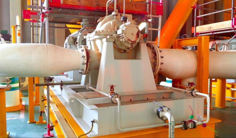
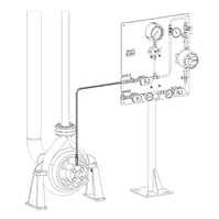 When you’re processing contaminated, polymerizing, or oxidizing fluids, or fluids with poor lubricity or high temperatures, API Plan 32 is often the answer to keeping centrifugal pumps running reliably. The plan delivers a clean flush fluid from an external source into the seal chamber. Flush fluid is delivered at a pressure higher than the process pressure to minimize or prevent process fluid from contacting the seal. A close-tolerance throat bushing is typically used to ensure seal chamber pressure and help isolate the seal chamber from the process fluid. To achieve this, the flush fluid must be chemically compatible with the process fluid.
Matching API Plan 32 Seal Flush Flow Rate to the Process
To correctly configure an API Plan 32 and flush flow rate, you’ll need to understand the role the plan plays. If process fluid can damage seal faces, API Plan 32 isolates the mechanical seal from potential damage. If the process fluid is toxic or hazardous, API Plan 32 reduces the risk of process fluid leaking into the atmosphere. If you’re pumping high-temperature process fluids, API Plan 32 helps cool the seal chamber and mechanical seal.
Regardless of why you’re implementing API Plan 32, you’ll need to determine the correct seal flush flow rate. Too little fluid flow and you’re undermining the reliability of the mechanical seal. Too much fluid flow and you’re driving up operating costs by consuming more flush fluid than required.
API Plan 32 Seal Flush Flow Rate for Seal Isolation
When you’re installing an API Plan 32 to isolate the mechanical seal from the process fluid, you’ll want to deliver flush fluid at a velocity or pressure that prevents process fluid from migrating past the throat bushing into the seal chamber. You can start by checking the recommended flow rates under different conditions provided by the mechanical seal manufacturer.
Even better, your asset management system may have detailed records regarding pump types, process conditions, and API Plan 32 seal flush flow rates. This information is often the most practical way to determine the correct flow rate to achieve both the required flow across the seal faces and velocity across the throat bushing.
If you don't have this information at hand, there are some metrics that can get you on the right track. A target of 15 fps across the throat bushing is a good starting point to protect seal faces from process fluid. You may want to adjust that based on impeller shaft, bushing size and diametrical clearance, and volumetric flow rate past the shaft. Tighter bushing clearances will reduce flow rates.
If you decide to adjust the flush flow rate based solely on pressure, adjust it relative to seal chamber pressure. One approach recommends adjusting the flow by opening up the seal flush until the seal chamber pressure increases at least 10 psi. It’s not uncommon to increase the pressure beyond that, even approaching 25 psi above seal chamber pressure.
Another approach recommends a flush flow rate of 1 gpm for each inch of mechanical seal diameter for pumps running 3600 rpm. Regardless of the method you choose, you’ll want to limit flow rate to the lowest required to maintain seal reliability and minimize operating costs.
API Plan 32 Seal Flush Flow Rate Cooling Factor
In addition to isolating the seal chamber from process fluid, mechanical seal friction or high-temperature applications may require a higher flush flow rate than calculated solely for isolation purposes. If the process is close to its boiling point, allocate no more than one-quarter of the available flush fluid temperature margin when calculating the flow rate.
In high-temperature process streams, the flush liquid may have a higher vapor pressure than process fluid at the same temperature. Introducing liquid with a lower boiling point into the process fluid may diminish pump capacity as a result of lower NPSHA at the impeller. Slight adjustments to the flush flow rate to increase cooling and minimize vaporization may be required to avoid the worst case—vapor lock.
Determine the Correct Flush Flow Rate With the Help of an Experienced Field Engineer
As you can see, determining the correct API Plan 32 flush flow rate involves careful consideration of multiple factors. Beginning with the purpose for choosing the plan—isolation and/or heat removal—you’ll also need to factor in:
- Mechanical seal manufacturer’s flow rate recommendations
- Any time-tested, real-world information available from your asset management system
- Type and cost of flush fluid—API Plan 32 can have significant operating costs, especially if you’re using an HCGO or HVGO flush.
- Size/volume of the seal chamber
- Throat bushing geometry—clearance and length
If you’re experiencing problems with pumps supported by API Plan 32 and don’t have the in-house expertise to quickly diagnose the problem, a local, experienced fluid systems field engineer can provide you with the needed guidance. Their experience in understanding how process conditions and flush fluid properties influence seal support system design is critical in determining the proper seal flush flow rate.
With their guidance, you’ll arrive at an API Plan 32 seal flush flow rate that maintains the proper seal chamber environment to prevent mechanical seal damage while minimizing the associated operating costs.
Local Expertise for All Areas of Mechanical Seal Support
For more than five decades, Swagelok has been a key partner in providing expertise and guidance in the use of seal support systems for Northern California process industries. Our field engineers are available to meet onsite to assess your needs, recommend seal support systems specifically configured for your pumping processes, and fabricate and test the systems in our local facilities before delivering them.
To find out more about how Swagelok Northern California can assist you in determining the right API Plan 32 seal flush flow rate or help in designing seal support systems that boost pump reliability, contact our team today by calling 510-933-6200.
-1.jpg?width=192&name=image8%20(1)-1.jpg) About Malik Durojaiye | Field Engineer, Assembly Services
About Malik Durojaiye | Field Engineer, Assembly Services
Malik Durojaiye began his Swagelok career in 2019 as a Custom Solutions Engineer in our Assembly Services group. Prior to Swagelok, Malik developed as a design engineer as well as a manufacturing engineer for 6 years serving Kentucky and California with Altec Industries; a leading provider of products and services to the electric utility, telecommunications, tree care, lights and signs, and contractor markets.