
.webp?width=210&height=70&name=StickyLogo%20(5).webp "Swagelok Northern California home page")
Share this
by Jeff Hopkins on 1/30/19 8:45 AM
For many professionals, pressure regulators are a complete mystery and a source of frustration. Let's demystify regulators and help you effectively use them in applications.
Have you wondered “what size regulator do I need to get flow to X at a set pressure of Y?” or “when we changed the flow the outlet pressure of the regulator changed, what gives?"
If so, you're not alone. We receive those questions at least once a week!
To break down pressure regulators—how they work, key principles, and selection tips for optimal fluid system performance—I'll start with a fundamental principle: fluids in the gas phase are compressible and follow the rules of the ideal gas law.
Ideal Gas Law
P*V=n*R*T (Pressure, Volume, number of moles, Gas Constant, Temperature)
- Fluids in the liquid phase are effectively incompressible, so they don’t really change volume when pressure changes
- Pressure is an expression of force over area, and fundamentally related to the number of collisions of the fluid on the walls of its container.
- Flow is the result of a fluid equalizing itself from a higher pressure to a lower pressure. The pressure and cross-sectional area of the tube or other space in which the flow is occurring determines the velocity of the physical molecules.
- Velocity is inversely proportional to pressure, meaning the faster a fluid travels, the more pressure is reduced.
Controlling pressure
If you watched our When Will it Burst? video series, you are probably very aware of the need to control pressure in a fluid system. Perhaps you are reducing the pressure coming out of a bottle of compressed gas, reducing facility gas pressure at the point of use, controlling the discharge of a pump or compressor, or controlling the pressure coming from a bulk gas or steam system as liquid is boiled into gas.
In almost all of these cases, the spring-loaded pressure regulator reigns supreme. There are other types of pressure regulation devices such as dome loaded regulators and electronic pressure controllers, but we'll save those discussions for another time.
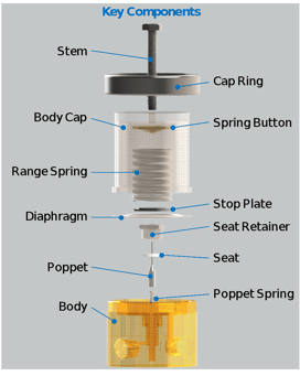
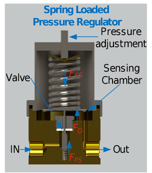
A regulator in many ways is a needle valve with a control diaphragm attached to it. A fixed spring pushes the valve closed, while a variable spring pushes on the diaphragm to allow the valve to open. Regulator valve position is determined by the equilibrium state of the three forces in the regulator acting against the valve:
FD – Force of the diaphragm, FSS – Force of the set spring, and FPS – Force of the poppet spring

FPS + FD = FSS
Say the pressure regulator is operating in steady state flow at a fixed set point when the downstream flow is increased. The increase in flow results in a decrease in downstream pressure, reducing force on the diaphragm:
FPS + FD ↓≠ FSS
The imbalance in total force on the valve means that the set point spring force is pushing the regulator valve down, opening it. This increases the flow through the regulator until the outlet pressure acts against the diaphragm bringing the forces back into equilibrium. By changing the force of the set point spring, the regulator pressure is effectively adjusted; turning the adjustment screw or knob clockwise tightens the spring, increasing set pressure. Turning it counterclockwise decreases set pressure.
Flow curves
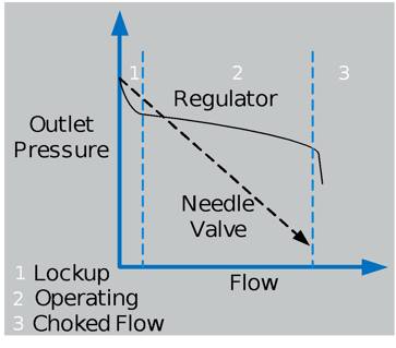 To properly select a pressure regulator, one of the most important things is to be able to read and understand flow curves. A regulator will change flow to maintain downstream pressure. As downstream pressure goes up or down, the regulator will change its valve position to compensate.
Since a regulator has mechanical limitations, it has droop associated with its operation. That means the regulator will never stay at the same pressure as flow changes throughout the range. A regulator can dampen this effect only by changing its valve position. Contrast this with a non-regulated valve like a needle valve and the effect on outlet pressure is far more dramatic.
"To properly select a pressure regulator, one of the most important things is to be able to read and understand flow curves."
For pressure regulators, the flow curve typically consists of three parts: lockup (also called seat load drop), operating range, and choked flow. When too much pressure builds up, the regulator will close off the inlet, or lock it up. A dead giveaway of lockup is chattering or pulsating sounds coming from the regulator. When pressure drops too far, the regulator valve is fully open and the regulator is effectively no longer operating. In this condition increasing flow only means greater pressure drop from the regulator.
The ideal part of a regulator’s operating curve is the "Goldilocks" zone, right in the middle of the operating range where the valve has the most control.
Turndown
 An incredibly important and commonly overlooked factor in the function of a pressure regulator is the turndown ratio. Effectively it's the ratio of inlet pressure to outlet pressure. The higher the ratio, the larger the range of flow your regulator will have. This effect is primarily driven by the expansion of the gas across the regulator valve. (For regulators operating in a liquid stream, this is pretty much irrelevant.)
The greater the expansion of gas across the regulator valve, the less the regulator’s valve has to move to change outlet pressure. Most pressure regulators don’t have a significant amount of valve movement to reach the end of travel. Generally, though not universally, it’s best to operate with at least a 10:1 turndown ratio, especially when operating at pressures under 100 PSIG. If you’re unable to have a 10:1 ratio, make sure you identify a regulator capable of operating with an extremely low turndown.
Check your references
There are far more factors that can influence the performance of a pressure regulator, including the Joule-Thompson effect, the Supply Pressure Effect, density or specific gravity of the media inside, and many more not mentioned here. Swagelok has amassed a large amount of performance data for our pressure regulators and detailed charts are readily available.
If you have our eDTR software, navigate to the “Technical” link under the “Regulators” link at the end. If you look up Pressure Regulator Flow Curves Technical Bulletin (MS-06-114), you’ll find 216 pages of operational explanations and flow curves on both gas and liquid. There are a significant number of flow curves in this reference that are not in the regulator catalog. If you don’t have our eDTR software, you can request one or you can access the tech bulletin through the Regulators Technical section of our eCatalog or you can download it directly from our flow curves landing page.
If you have ever looked at our regulator catalog you likely noticed that the standard K-series regulator has a staggering 16-digit configurable part number. When combined with all the different types of regulators in the catalog, you wind up with about 10 million possible combinations. The bad news is that we can stock only a small fraction of those combinations. The good news is that there is an 80 percent chance we will have the range of pressure regulator you need in stock.
Need your regulator pre-assembled and ready to install? Check out our Swagelok regulator assemblies.
Webinars on this topic: