
.webp?width=210&height=70&name=StickyLogo%20(5).webp "Swagelok Northern California home page")
Share this
by Malik Durojaiye on 4/20/21 8:45 AM
Many pumping processes in refineries circulate high-temperature, heavy hydrocarbons. The mechanical seals in many of these pumps often require a seal support quench system to prevent coking—which occurs when hydrocarbon particulates come into contact with air. Seal support quench systems are also leveraged to cool the seal or dilute any hydrocarbon leakage that makes its way across the seal faces to the atmosphere. In some medium-temperature hydrocarbon pumping processes, a quench is needed to heat the seal faces. For pumping processes operating below 0°C, a nitrogen quench is applied to prevent the atmospheric side of a mechanical seal from icing. A seal support quench system can be a low-cost alternative to dual/tandem mechanical seal configurations.
Quench fluid can be steam, water, or even nitrogen, depending on the process conditions. The quench is delivered to the atmospheric side of the mechanical seal. Steam is typically used in processes where solid hydrocarbon particles or water-soluble particles can form. Particulates that are removed via the quench are then drained into a collection system.
To get a better understanding of how a quench is delivered, let’s quickly look at two seal support quench systems: API Plan 51 and API Plan 62.
 |
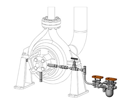
API Plan 51
|
|

|
API Plan 62
|
|
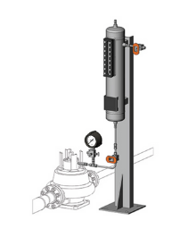
Either of these two plans can also have a leakage collection system added. API Plan 65A is connected to the drain port on the gland and a reservoir collects normal leakage of condensing process fluid. The reservoir is kept constantly open to drain the collected fluid. The system monitors leakage and in the event of a seal failure, an orifice fitting on the system outlet lets a level transmitter trigger an alarm.
API Plan 65B connects to the gland drain port and collects normal leakage of condensing process fluid into a reservoir. In the event of excessive leakage, a level transmitter on the reservoir triggers an alarm. An outlet valve on the reservoir is typically left closed and opened only when there is a need to drain the reservoir.
Seal Support Quench System Design Decisions
Although these four API plans appear relatively simple in comparison to many other API plans, to obtain the best long-term performance from any seal support quench system, it’s best to work with experienced fluid system engineers. They bring the expertise needed to evaluate the pumping process, including process conditions, pump rating, type of mechanical seal, and available plant services. With that information, they can then begin to design the optimum quench system for the process. Critical seal support quench system design decisions may include:
- Avoiding contamination of bearings immediate to the gland plate by the steam or water quench by recommending a close bearing bushing and drainage system or a bearing bracket oil condition monitoring bottle
- Calculating the required reservoir volume and flow rate for API Plan 51 to ensure reliability and minimize the frequency of quench fluid replenishment
- Specifying the appropriate steam pressure (typically 3 to 5 psi) to remove solid accumulation from the atmospheric side of the seal
- Determining the correct steam temperature to avoid increasing the process temperature which would result in vapor pressure increases within the stuffing box
With a properly designed seal support quench system, you can avoid costly problems that undermine the efficiency and reliability of critical pumps. You can also increase mechanical seal life and reduce MTBF for the pump by making the up-front investment in working with an experienced fluid systems engineer.
Swagelok: Global Expertise Applied to Local Process Needs
Whether you are planning a new pump installation or need to upgrade an existing pump because of changing process conditions, Swagelok brings more than five decades of fluid systems experience, including top-quality component manufacturing, best practices in system design, and ongoing technical support. We will work side-by-side with you to make sure your seal support quench system is properly designed, carefully assembled, and thoroughly tested prior to delivery. Our local field engineers are backed by a team of experienced professionals who have solved some of the most challenging seal support problems around the world.
To find out more about how Swagelok Northern California can help you obtain the best performance from seal support quench systems by providing expert on-site consultation and assembly services, contact our team today by calling 510-933-6200.
-1.jpg?width=192&name=image8%20(1)-1.jpg) About Malik Durojaiye | Field Engineer, Assembly Services
About Malik Durojaiye | Field Engineer, Assembly Services
Malik Durojaiye began his Swagelok career in 2019 as a Custom Solutions Engineer in our Assembly Services group. Prior to Swagelok, Malik developed as a design engineer as well as a manufacturing engineer for 6 years serving Kentucky and California with Altec Industries; a leading provider of products and services to the electric utility, telecommunications, tree care, lights and signs, and contractor markets.