Share this
Getting Accurate Results from Analyzers (+3 Downloads)
by Jeff Hopkins on 6/6/18 12:00 PM
Measuring (and understanding) delay from the tap to the analyzer
"Time delay in sample systems is the most common cause of inappropriate results from process analyzers."
- Doug Nordstrom, Swagelok Company and Tony Waters, Sampling System Expert
Process measurements are instantaneous, but analyzer responses never are. From the tap to the analyzer, there is always a delay. That delay in sample systems is the most common cause of inappropriate results from process analyzers.
The industry standard is a one-minute response. Less is even better, but delays beyond a minute are not necessarily a problem. The process engineer determines acceptable delay times based on process dynamics. Delays become an issue when they exceed a system designer’s expectations.
In this first of three posts about getting accurate results, we'll look at some causes of time delay. You'll find links to three valuable resources too.
Delays add up
The potential for delay exists in the process line, the tap and probe, the field station, the transport line, the sample conditioning system, the stream switching system, and the analyzer itself. It's important to understand that time delay is cumulative. It consists of the total amount of time it takes for fluid to travel from the latest step in the process line to the analyzer, including time required for analysis.
To minimize time delay, locate the tap as close to the analyzer as possible, although there are other variables to consider. For example, the tap should be located upstream of sources of delay, such as drums, tanks, deadlegs, stagnant lines, or redundant or obsolete equipment. The tap location also should provide enough pressure to deliver the sample through the transport lines or fast loop without a pump.
But in many cases you can't dictate the location and you have to make do with what you have. If the tap is at a long distance from the analyzer, a fast loop can quickly deliver fluid to the analyzer. If properly designed, flow in the fast loop will be much faster than flow in the analyzer lines.

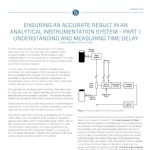
Ensuring an Accurate Result in an Analytical Instrumentation System, Part 1
The probe
Probes can be another source of time delay. The larger the probe’s volume, the greater the delay. The probe should be long enough to reach to the “middle third” of the process line diameter, where the stream moves the fastest and provides the cleanest, most representative sample.
Fluid velocity in the probe cannot be measured directly but it can be calculated. Don't assume that velocity in the probe is the same as in the transport lines. In some cases, the difference is quite dramatic because the size of the tubing or pipe is different. In addition, in the case of a gas, higher pressure in the probe than the transport lines means slower flow.
The field station
In the case of gas, a field station is used to reduce pressure in the transport lines or fast loop. Given the same flow rate, time delay in the transport lines is reduced in direct proportion to the reduction in absolute pressure. At half the pressure, you will get half the time delay.
Put the field station as close to the tap as possible. The sooner the pressure is dropped, the better.
A regulating field station is not used for liquids. It is better to keep liquids at high pressure to keep bubbles from forming. But when a liquid sample will be analyzed as a gas, a vaporizing regulator may be used at the field station. A vaporizing regulator will cause considerable time delay. As the fluid changes from liquid to gas, volume will increase dramatically. The rate of increase will depend on the liquid’s molecular weight.

Industrial Sampling Systems book excerpt
Stream switching
From a time-delay perspective, stream switching assemblies must work fast, quickly purging old sample material while moving the new stream to the analyzer. Double block and bleed valve (DBB) configurations provide a means of switching streams with minimal deadlegs and no cross-stream contamination from leaking valves.
The traditional cascading DBB configuration can produce a tortuous flow path, which leads to pressure drop and slower flow. Using a DBB configuration with an integrated flow loop offers all the advantages of cascading configuration while ensuring minimal pressure drop consistently across all streams.

Process Analyzer Sampling System Training brochure
Sampling conditioning systems
The sampling conditioning system prepares the sample for analysis by filtering it, by ensuring it is in the right phase, and by adjusting pressure, flow, and temperature. It involves a lot of components, including gauges, regulators, variable area flowmeters, flow controllers, check valves, control valves, and ball valves.
As with stream switching valves, the critical matter here is not internal volume so much as pressure drop.
Other components used in the sampling conditioning systems, such as filters, knockout pots, and coalescing filters, may cause significant time delay because they allow incoming samples to mix with old samples. To clear out a filter or knockout pot – so 95 percent of the old sample is gone – requires three times the volume of the component. That’s assuming the inlet and outlet are adjacent.
The analyzer
As a rule of thumb, a gas chromatograph will take five to 10 minutes to analyze the sample. Infrared and ultraviolet analyzers work much faster, completing analyses within seconds. However long it takes, that time must be added to the estimates discussed above for the total time delay from tap through the analyzer.
Stream switching
We have a free, eight-page technical paper, Ensuring an Accurate Result in an Analytical Instrumentation System, Part 1, that covers this information in much greater detail, including more examples. For even more information, see the Swagelok book Industrial Sampling Systems, the definitive sampling systems reference guide by expert Tony Waters.
Next up: We'll look at how proper calibration can make a big difference in accuracy.
More like this:
- Tony Waters Wrote the Book on Industrial Sampling Systems (blog article)
- Technical Webinar: Pre-Engineered Subsystems (PDF download & webinar replay page)
- More Swagelok technical articles on analytical instrumentation (section of this site)
Share this
- Archive (465)
- Assembly Services (207)
- About (100)
- Seal Support Systems (96)
- Best Practices (88)
- Training Services (74)
- Fittings (51)
- Semiconductor Applications (49)
- Hoses and Flexible Tubing (47)
- Regulators (44)
- Tubing (42)
- Grab Sampling Systems (32)
- Sampling Systems (32)
- Gas Systems (30)
- Services (30)
- Downloads (29)
- Valves (24)
- Application Support (18)
- Orbital Welding (17)
- Case Studies (13)
- Steam Systems (13)
- Frequently Asked Questions (12)
- Tools (12)
- Measurement Devices (7)
- Subsystems (6)
- Thermal Management (6)
- September 2023 (1)
- August 2023 (2)
- June 2023 (1)
- March 2023 (3)
- February 2023 (3)
- January 2023 (4)
- December 2022 (4)
- November 2022 (4)
- October 2022 (4)
- September 2022 (1)
- August 2022 (3)
- July 2022 (2)
- June 2022 (4)
- May 2022 (1)
- April 2022 (2)
- March 2022 (1)
- February 2022 (2)
- January 2022 (3)
- December 2021 (1)
- November 2021 (6)
- October 2021 (6)
- September 2021 (8)
- August 2021 (4)
- July 2021 (3)
- June 2021 (6)
- May 2021 (6)
- April 2021 (7)
- March 2021 (5)
- February 2021 (4)
- January 2021 (6)
- December 2020 (5)
- November 2020 (6)
- October 2020 (6)
- September 2020 (8)
- August 2020 (7)
- July 2020 (8)
- June 2020 (8)
- May 2020 (6)
- April 2020 (9)
- March 2020 (7)
- February 2020 (10)
- January 2020 (21)
- December 2019 (23)
- November 2019 (21)
- October 2019 (22)
- September 2019 (21)
- August 2019 (22)
- July 2019 (23)
- June 2019 (20)
- May 2019 (23)
- April 2019 (22)
- March 2019 (21)
- February 2019 (20)
- January 2019 (21)
- December 2018 (14)
- November 2018 (19)
- October 2018 (23)
- September 2018 (17)
- August 2018 (29)
- July 2018 (11)
- June 2018 (6)
- May 2018 (5)
- April 2018 (4)
- March 2018 (5)
- February 2018 (3)
- January 2018 (3)
- December 2017 (2)
- November 2017 (4)
- October 2017 (3)
- September 2017 (2)
- August 2017 (6)
- July 2017 (4)
- June 2017 (4)
- May 2017 (4)
- April 2017 (3)
- March 2017 (4)
- February 2017 (3)
- January 2017 (3)
- December 2016 (3)
- November 2016 (3)
- October 2016 (3)
- September 2016 (5)
- August 2016 (5)
- July 2016 (4)
- June 2016 (5)
- May 2016 (3)
- April 2016 (4)
- March 2016 (5)
- February 2016 (11)
- January 2016 (1)
- December 2015 (3)
- November 2015 (4)
- October 2015 (3)
- September 2015 (4)
- August 2015 (4)
- July 2015 (8)
- June 2015 (5)
- May 2015 (3)
- April 2015 (4)
- March 2015 (4)
- February 2015 (3)
- January 2015 (4)
- December 2014 (2)
- November 2014 (3)
- October 2014 (4)
- September 2014 (4)
- August 2014 (4)
- July 2014 (5)
- June 2014 (4)
- May 2014 (4)
- April 2014 (5)
- March 2014 (4)
- February 2014 (3)
- January 2014 (4)
- December 2013 (5)
- November 2013 (3)
- October 2013 (4)
- September 2013 (3)
- August 2013 (5)
- July 2013 (5)
- June 2013 (5)
- May 2013 (3)
- April 2013 (6)
- March 2013 (4)
- February 2013 (4)
- January 2013 (8)
- December 2012 (4)
- November 2012 (6)
- October 2012 (6)
- September 2012 (4)
- August 2012 (4)
- July 2012 (4)
- June 2012 (4)

.webp?width=210&height=70&name=StickyLogo%20(5).webp)

