
.webp?width=210&height=70&name=StickyLogo%20(5).webp "Swagelok Northern California home page")
Share this
by Morgan Zealear on 8/14/21 10:45 AM
Essential information about our grab sampling systems and a selection matrix to help you choose.
Managing any complex fluid system requires regular sampling and analysis of the process fluid. For sample analysis to be useful, though, the sample must be taken properly to represent the process and be compatible with the analyzer. Not every system is appropriate for every application, so selecting the right grab sampling equipment for your application conditions is important.
Swagelok offers two types of Grab Sampling Systems: Grab Sample Modules and Grab Sample Liquid systems. Check out information and a grab sampling diagram for each below, then use our selection matrix to help you decide which system is right for your application.
Grab Sample Module
The Grab Sample Module (GSM) captures either liquid or gas in a sealed, pressure-containing cylinder (also known as a gas sampling bomb). Closed-loop sampling provides a fresh sample extracted and held under the same process pressure as at the time of sampling.
The GSM closed-loop sampling system draws the fluid from a positive-pressure process and recirculates it to the process at a lower-pressure location, such as upstream of a pump. This pressure differential keeps the fluid moving through the GSM, allowing the system to remain in position indefinitely. This also keeps fresh process fluid in the sampling lines so they are always ready to draw a sample without needing to be flushed.
GSM Configuration and Grab Sampling Diagram
Which GSM configuration is used for an application depends mainly on the phase of the process fluid. When sampling a liquid, vapor rises to the top of the cylinder, so it should be configured to fill from the bottom up. This purges any vapor from the cylinder, ensuring it is full of liquid. Likewise, gas samples should be filled from the top down to push out any condensed liquids.
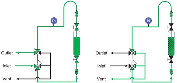
The grab sampling diagram above shows a simple GSM configuration. Process fluid flows through the sample cylinder to the outlet port while the valves are in the sample position (left). When sampling is complete and the cylinder is closed, turning the handle to the vent position (right) isolates the supply/return lines and vents the fill lines. GSMs configured for gases fill from the top of the cylinder instead of the bottom. Other configurations include options such as purge or continuous flow.
Liquid-Only Sampling Module
The Grab Sample Liquid (GSL) is a system for drawing a liquid sample into an unpressurized bottle. This system can only be used with non-volatile liquids. Bottles are inexpensive, easily replaced, and feature cheap, replaceable self-sealing septum caps to prevent spilling and evaporation.
Fixed-volume sampling is an optional safety feature that completely separates the sample bottle from the pressurized process fluid, preventing overfilling and protecting the user.
Swagelok GSL systems feature Sentry Equipment's manual valve sampler, which has a spring-return handle to prevent unintentional dispensing. Our GSL systems are designed for Boston round or media bottles but can accommodate other bottle geometries and materials as well.
GSL Configurations and Grab Sampling Diagram
Typically, a GSL is only used with water or other low-vapor pressure liquids. Bottles can only contain a small amount of pressure without leaking. If the application is suitable for bottle sampling, the next step is to determine whether continuous flow or purging is required or if a fixed-volume option is more appropriate.
Continuous flow is useful when the sample requires constant motion or if there is a long tubing run leading to the sample point. Continuous flow ensures the fluid has not been sitting in the tubes for an extended time before it is sampled.
When continuous flow is not an option or the fluid has the potential to solidify, a purge option can clean the dispensing needle and internal tubing. The fixed-volume option should be considered if the process fluid is hazardous or under high pressure.
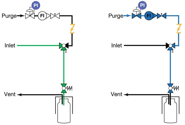
In this grab sampling diagram of a GSL configuration, process fluid flows through the bottle and the vent equalizes pressure in the jar to let the air out (left). In the purge position (right), a purge fluid flushes the fill lines in the direction of filling and allows the bottle to vent.
Grab Sampling System Selection Matrix
This table provides a summary of common system criteria and the grab sampling system recommended for each combination.
| Pressurized Storage | Sample Receiver | Sample Phase | Continuous Flow | Purge | Fixed Volume | Back Purge | Ordering Number |
| Yes | Cylinder | Liquid | No | No | Yes | No | GSM-L-1(-N) |
| Yes | Cylinder | Liquid | No | Yes | Yes | No | GSM-L-1(-P) |
| Yes | Cylinder | Liquid | Yes | No | Yes | No | GSM-L-2(-N) |
| Yes | Cylinder | Liquid | Yes | Yes | Yes | No | GSM-L-2(-P) |
| Yes | Cylinder | Gas | No | No | No | No | GSM-G-1(-N) |
| Yes | Cylinder | Gas | No | Yes | No | No | GSM-G-1(-P) |
| Yes | Cylinder | Gas | Yes | No | No | No | GSM-G-2(-N) |
| Yes | Cylinder | Gas | Yes | Yes | No | No | GSM-G-2(-P) |
| No | Bottle | Liquid | No | No | No | No | GSL1 |
| No | Bottle | Liquid | No | Yes | No | No | GSL2 |
| No | Bottle | Liquid | Yes | No | No | No | GSL3 |
| No | Bottle | Liquid | Yes | Yes | No | No | GSL4 |
| No | Bottle | Liquid | No | Yes | No | Yes | GSL5 |
| No | Bottle | Liquid | No | No | Yes | No | GSL6 |
| No | Bottle | Liquid | Yes | No | Yes | No | GSL7 |
| Check out Swagelok’s Grab Sampling Systems Application Guide for more detailed grab sampling diagram examples, or download additional literature to learn about how we can tailor systems to your needs. |
Local Grab Sampling System Assembly and Support
Our engineers are experts on grab sampling and can perform an onsite consultation to make recommendations specific to your needs. From there, we can design, verify, fabricate, and test a grab sampling system optimized for your process—all backed by Swagelok’s industry-leading Lifetime Warranty.
We’re always available for ongoing technical support, maintenance strategy guidance, and spares at a moment’s notice. Swagelok’s proximity, standard-setting design practices, superior component quality, and certified assembly teams are ready to meet the grab sampling needs of Northern California refineries.
To find out more about how Swagelok Northern California can help with your grab sampling needs, contact our team today by calling 510-933-6200.
 Morgan Zealear | Product Engineer – Assembly Services
Morgan holds a B.S. in Mechanical Engineering from the University of California at Santa Barbara. He is certified in Section IX, Grab Sample Panel Configuration, and Mechanical Efficiency Program Specification (API 682). He is also well-versed in B31.3 Process Piping Code. Before joining Swagelok Northern California, he was a Manufacturing Engineer at Sierra Instruments, primarily focused on capillary thermal meters for the semiconductor industry (ASML).