
.webp?width=210&height=70&name=StickyLogo%20(5).webp "Swagelok Northern California home page")
Share this
by Jeff Hopkins on 5/17/18 8:30 AM
A peek at how Swagelok Northern California pro Jason Burns uses Cv and Swagelok tools to size system components, using our free Cv Calculator tool, and more.
 Flow Coefficient (Cv: US units) & Flow Factor (Kv: SI units) is an operator used to determine the approximate flow or pressure drop across a flow restriction like a valve. Cv can also be worked backward to determine the approximate flow for a given pressure drop. A detailed technical bulletin on Cv and valve sizing is available here at our site.

For this exercise, we’ll use the Swagelok Cv for water flow through a ball and needle valves. Almost every Swagelok valve product has a published CV in the product datasheet as well as the catalog.

Delivery pressure in chill water systems
Frequently in chill water cooling systems, delivery pressure is predetermined and unchangeable. To select the proper valves you need to ensure that fluid velocity isn’t too high, resulting in elevated pressure drop and insufficient cooling flow. With a quick verification, ½” tube seems to be sufficient enough through right at the maximum allowable velocity.
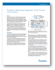
 Almost every Swagelok valve product has a published Cv in the product datasheet as well as the catalog. Swagelok Tube Fitter’s Manual appendices contain several charts showing pressure drop versus flow rate for various tube sizes for air and water. It’s a good idea if you have a long run of tubing to double check estimated pressure drop on the curves and up/downsize lines as necessary.

A typical liquid cooling system usually has nine valves between the supply and return headers on the facility sides. Each valve in the flow path will have a pressure drop associated with it, which will result in a total system pressure drop. When selecting valves, the Cv calculator can be used to estimate the pressure drop of each valve.
Calculating pressure drop
Let’s say we are looking at the pressure drop for valve ▲P4 and ▲P5. We’ll make the assumption that the first three valves already reduced water pressure by 5 PSIG, and our initial pressure is 55 PSIG. For the ▲P4 isolation valve, I want to use a ½” 60 Series ball valve (SS-63TS8), which has a Cv of 7.5.
I expect the pressure drop to be fairly low, so I’ll enter the inlet pressure of 55PSIG and the outlet pressure only 1 PSI lower than the inlet, and then gradually change outlet pressure recalculating Cv until I’m close to the rated Cv of the valve.
The screen shots I'd planned to include here are a bit small to read, but the resulting estimated value of ▲P4 is 0.16 PSID. The needle or flow control valve we will have a much lower Cv, so with the inlet pressure set to 54.84 PSIG we’ll try to match the Cv of 1.8 on the 18 Series integral-bonnet needle valve (SS-18RS8) starting with a 5 PSIG drop.
Result: 2.78psig at 3gpm
After hunting around a bit ▲P5 comes out to approximately 2.78 PSIG at the required flow rate of 3GPM. As you may have noticed, you can also use a rated CV value with inlet and outlet pressures to calculate the estimated flow rate through a valve if you know the inlet and outlet pressures. This can be useful in applications such as injecting a gas or liquid into an already pressurized system where you want to size the injection valve for a specific flow range.
 About Jason Burns, Technical Service Manager
Jason Burns has been with Swagelok Northern California for over 25 years. From warehousing, customer service, inventory management, technical service, and even product training, Jason pulls from his past experiences to provide fast and accurate technical information to customer related applications.
 Fluid system design tools
Don't miss our Resources section on design. You'll find a free Cv calculator tool, over 1 million free CAD files and sales drawings, a free flow curve generator tool, and more.

More like this: